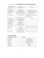
WT-1550-DM Intelligent Direct Modulated Optical Transmitter
- 6 -
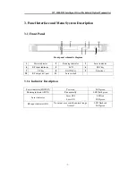
3.2
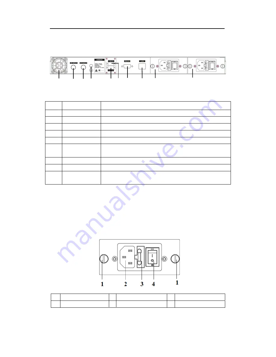
Rear Panel
Rear Panel schematic diagram
No.
Name
Remark
1
Fan
2
RF input
3
Local RF input
Generally reserved
4
Ground stud
Used for the connection of device and ground wire
5
Optical input
Inserted optical signal input (without inter-cut function, no this port)
6
Optical signal
output
This interface is the optical signal output port of the device (If select
inter-cut function, this port is mixed output)
7
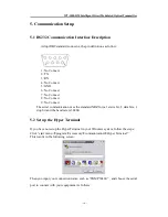
RS232 interface
Used for configuring the network management parameters.
8
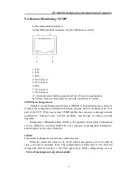
LAN interface
Correspond to IEEE802.3 10Base-T, used for network management.
9
Switching power
supply
Hot plug
3.3
Power Module
3.3.1 220V Power Module
1
Mounting screws
2
220V/110V power outlet
3
Fuse
4
Power switch
1
2
3 4
5
6
7
8
9
9


