5-30 OTHER FEATURES
PA1628 H3-41, H3-45 Operator’s Manual
WARNING
The coolant heating system uses the same
fuel as the engine. Do not operate in a
closed building or while refueling. Operate
only in a well-ventilated area.
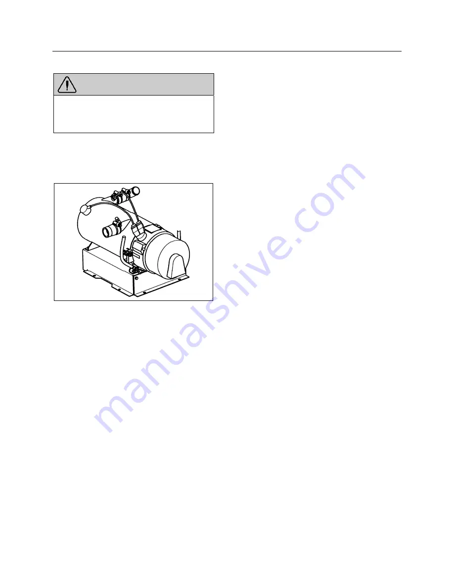
The coolant heater is located in a compartment
in the lower part of the rear electrical
compartment. To access the coolant heater,
remove the panel in the rear electrical
compartment.
COOLANT HEATER (104,000 BTU)
22224
SWITCHING THE HEATER ON
The timer light illuminates when the heater is
switched on. Air is forced in to flush out the
combustion chamber of residual gases and the
water circulation pump begins operating. The
fuel metering pump delivers fuel in precise
amounts to the combustion chamber, where
fuel and combustion air form a combustible
mixture which is ignited by the ignition unit.
Once the flame sensor has signaled to the
control unit that combustion has taken place,
the ignition unit is switched off.
Hot combustion gases are diverted at the end of
the flame pipe and are then forced through the
indirect heating surfaces of the heat exchanger.
The heat exchanger transfers the heat to the
coolant water passing through the heat
exchanger.
The heater is thermostatically controlled and
operates intermittently (i.e., the switched-on
time of the burner varies depending on the heat
requirement). The water temperature is
controlled by the built-in water thermostat.
The water circulation pump remains in operation
as long as the heater is operating, even during
the regulated intervals and during the delayed
cut-out of the heater. The pump can also be
operated independently of the heater by means
of an appropriate circuit. The heater can be
switched
ON
at any time (i.e., during the delayed
cut-out period). Ignition takes place after the
delayed cut-out time expires.
SWITCHING THE HEATER OFF
The fuel supply is interrupted when the heater is
switched
OFF
. This causes the flame to go out
and a delayed cut-out of 2.5 minutes begins.
The circulating combustion air flushes the
remaining combustion gases out of the chamber
and cools off the heated parts on the exhaust
side of the heat exchanger. The water
circulation pump continues to transfer the
latent heat present in the heat exchanger, thus
preventing hot spots. Once the delayed cut-out
time expires, both the combustion air blower
and the water circulation pump switch
OFF
automatically. A cut-out will automatically take
place in case of heater failure. Refer to Section 9
Technical information
for additional information.
COOLANT HEATER TIMER
The timer, located on L.H. lateral console is used
to program the starting and stopping time of
the preheating system and to give Fault Codes.
The system indicator light, located on the timer,
illuminates when the system is functional.
Summary of Contents for H 2018 Series
Page 1: ...COACH MANUFACTURER OPERATOR S MANUAL H SERIES COACHES PA1628 January 2018 ...
Page 8: ......
Page 10: ......
Page 14: ......
Page 30: ......
Page 114: ......
Page 217: ...TECHNICAL INFORMATION 9 5 PA1628 H3 41 H3 45 Operator s Manual H3 45 OVERALL DIMENSIONS 18525 ...
Page 232: ......
Page 236: ......
Page 256: ......


