SAFETY FEATURES AND EQUIPMENT 7-11
PA1628 H3-41, H3-45 Operator’s Manual
Lower Alternator Failure
1.
Raise the belt tensioner. Use a breaker bar
with a ¾ inch drive to rotate the tensioner
pulley upward and relieve alternator belt
tension. Remove belt;
2.
Install the limp-home drive belt on the drive
and top alternator pulleys first;
3.
Complete installation of the limp-home belt
as shown;
4.
Slide the belt on the idler pulley.
5.
Gently release the belt tensioner.
NOTE
To prevent the batteries from being
discharged, the HVAC system will turn OFF
automatically if the battery state of charge
falls below 50%.
LIMP-HOME BELT ON TOP ALTERNATOR
01194
SPARE WHEEL
The spare wheel and tire is located in a
compartment behind the reclining front bumper.
In case of a flat tire:
Turn ON the hazard flashers;
Bring the coach to a stop on the side of the
road;
Apply the parking brake;
Make sure the coach is parked safely away
from traffic;
Set up the triangular reflectors in accordance
with applicable highway regulations.
CHANGING A WHEEL
To access the spare wheel compartment, lower
the front reclining bumper. To do so, pull on the
release handle located in the front electrical and
service compartment.
The bumper will lower gradually. When closing
the compartment, be sure the bumper is firmly
in place.
NOTE
The bumper is equipped with spring hinges to
allow handling by one person.
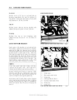
To remove the spare wheel from the
compartment:
1.
Loosen the screw holding the tire in place
(see image).
2.
Remove the wave pin and the clevis pin.
3.
Pull the spare wheel out of the
compartment using the strap.
REMOVING THE SPARE WHEEL
13038
Installation of the spare wheel
NOTE
The jack and tools are located in the first
baggage compartment.
1.
Loosen the wheel nuts about one turn;
2.
Raise the vehicle by the closest jacking point
(See “Jacking points” in this section);
Summary of Contents for H 2018 Series
Page 1: ...COACH MANUFACTURER OPERATOR S MANUAL H SERIES COACHES PA1628 January 2018 ...
Page 8: ......
Page 10: ......
Page 14: ......
Page 30: ......
Page 114: ......
Page 217: ...TECHNICAL INFORMATION 9 5 PA1628 H3 41 H3 45 Operator s Manual H3 45 OVERALL DIMENSIONS 18525 ...
Page 232: ......
Page 236: ......
Page 256: ......


