8-10 CARE AND MAINTENANCE
PA1628 H3-41, H3-45 Operator’s Manual
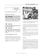
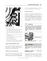
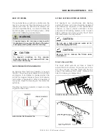
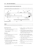
TRANSMISSION FLUID LEVEL DIPSTICK
07006
CAUTION
The oil level rises as oil temperature rises.
Do not add oil above the "cold run" band
before the transmission reaches 180
o
F to
220
o
F (82
o
C to 104
o
C).
Hot Check
Make sure the transmission fluid temperature is
between 180
o
F and 220
o
F (82
o
C and 104
o
C)
before performing the hot check. Run the engine
between 1,000 and 1,200 RPM for approximately
one minute to purge air from the system. With
the engine idling and the parking brake applied,
shift transmission from forward (D) to reverse
(R) and back into neutral (N) to fill clutch cavities
with oil. Remove and clean dipstick, then check
oil level. If the oil level is on or under the lower
HOT RUN line, add just enough oil to bring up
the level to the middle of the HOT RUN band.
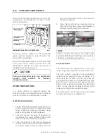
TRANSMISSION FLUID LEVEL DIPSTICK
07006
Replace dipstick and tighten the filler tube cap
until the rubber seal is correctly seated.
CAUTION
Do not overfill transmission fluid reservoir.
Severe damage may result.
I-SHIFT TRANSMISSION FLUID LEVEL
1.
Vehicle should be on horizontal ground
when oil is changed;
2.
Do not check oil level straight after a journey
(incorrect measurement). Undertake the
check once the transmission oil has cooled
down (lower than 104
o
F or 40
o
C);
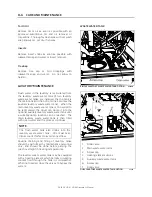
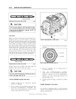
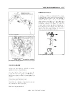
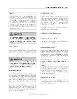
I-SHIFT TRANSMISSION OIL LEVEL CHECK
07111
3.
Check oil level using transmission sight glass
(item 2) ;
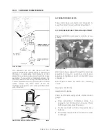
SIGHT GLASS FOR CHECKING OIL LEVEL
4.
Add oil through the oil filling point if
necessary (item 3) ;
5.
Only use VOLVO-approved synthetic
transmission oil in the I-Shift transmission.
Refer to section 24 of the Maintenance
Manual for more information about oils
approved by Volvo;
6.
Torque tighten fill plug to 26±4 Lb-Ft (35±5
N·m).
POWER STEERING FLUID LEVEL
The coach is equipped with a power steering
system. The hydraulic fluid tank is located in the
engine compartment.
Summary of Contents for H 2018 Series
Page 1: ...COACH MANUFACTURER OPERATOR S MANUAL H SERIES COACHES PA1628 January 2018 ...
Page 8: ......
Page 10: ......
Page 14: ......
Page 30: ......
Page 114: ......
Page 217: ...TECHNICAL INFORMATION 9 5 PA1628 H3 41 H3 45 Operator s Manual H3 45 OVERALL DIMENSIONS 18525 ...
Page 232: ......
Page 236: ......
Page 256: ......


