4
APPENDIX C – Allison Transmission’s Other Features
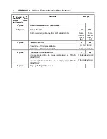
With the engine off and the ignition on, perform
the following sequence on the selector, N-R-N-
D-N-R-N-D-N-R-N-D-N.
The TRANSMISSION SERVICE indicator
flashes if TES389 is the current setting and
illuminates solidly if TES295 is the current
setting. To change the transmission fluid type,
wait 5 seconds after entering transmission fluid
type mode and perform the following sequences
to select the proper transmission type:
N-R-N to select TES295
N-D-N to select TES389
The selector exits 30 seconds after entering
transmission fluid type mode or the ignition may
be turned off to exit earlier. Only one
transmission fluid type selection may be made
after entering transmission fluid type mode. All
other attempt will be ignored. Transmission fluid
type mode needs to be entered again if the
wrong type of fluid is selected.
CAUTION
Verify prognostics fluid type setting matches
transmission fluid type. Oil Life Monitor
notifications will be inaccurate when
mismatched. This could result in transmission
damage from running a TES389 fluid too long
or cause shortened TES295 fluid changes to
occur.
CAUTION
Required calendar-based oil & filter change
intervals (based on month) still apply because
Oil Life Monitor function cannot measure time
while ignition power is OFF.
If the Oil Life Monitor function has not indicated
the need for a fluid change before 60 months
have passed when using TES295 fluid type or
before 24 months have passed when using
TES389 fluid type, it will be necessary to
change the fluid and filters per calendar
requirements and reset the system.
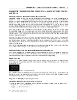
FILTER LIFE MONITOR
This feature provides an alert when the
transmission’s fluid filters need to be replaced. It
helps extend filter change intervals to reduce
routine maintenance downtime while providing
maximum protection for the transmission.
The filter life indicator pressure switch signals
the transmission control module when fluid
exiting the main filter drops below a
predetermined pressure. Both the main and lube
filters
must be
changed when the
TRANSMISSION SERVICE indicator
shows
the main filter should be changed.
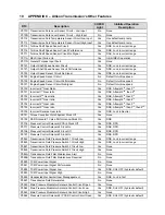
Filter Change Notification
Once the programmed threshold for maximum
filter pressure drop has been observed and
verified, the diagnostic code P088A
Transmission Filter Maintenance Alert will be
recorded to indicate that the filter has reached
the end of its designed life. At the next
initialization of the TCM, the TRANSMISSION
SERVICE indicator will flash for 2 minutes after
the first selection of “D” (drive) range.
Thereafter, the indicator will illuminate and flash
upon each TCM initialization, continuing to flash
for 2 minutes after the first selection of a drive
range each time, until service is performed and
the indicator is reset.
Failure to perform maintenance and reset the
monitor after a calibration-defined number of
warnings will result in the illumination of the
CHECK light with associated message in the
DID and diagnostic code P088B will be recorded
to indicate a highly deteriorated filter.
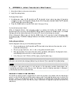
Read and Reset Filter Life Monitor from
Selector
To enter
the filter life monitor, press
simultaneously the
(Upshift) and
(Downshift) arrows three times. An acceptable
filter life status is displayed as "OIL FILTER OK".
An unacceptable filter life status is displayed as
"REPLACE FILTERS".
The feature will
reset
automatically when the
main fluid filter has been changed and the
pressure drop across the filter no longer
exceeds the threshold value. A manual reset
can be performed by depressing and holding the
MODE button for ten (10) seconds while the
Filter Life Monitor function is displayed. It may
also be reset by selecting N-R-N-R-N-D-N on
the shift selector, pausing briefly (less than 3
seconds) between each selector movement,
with the ignition on and the engine not running.
The TRANSMISSION SERVICE indicator
illuminates briefly following a reset to
acknowledge the reset was successful.
Summary of Contents for H 2018 Series
Page 1: ...COACH MANUFACTURER OPERATOR S MANUAL H SERIES COACHES PA1628 January 2018 ...
Page 8: ......
Page 10: ......
Page 14: ......
Page 30: ......
Page 114: ......
Page 217: ...TECHNICAL INFORMATION 9 5 PA1628 H3 41 H3 45 Operator s Manual H3 45 OVERALL DIMENSIONS 18525 ...
Page 232: ......
Page 236: ......
Page 256: ......


