STARTING AND STOPPING PROCEDURE
4 - 3
Its major components include an Electronic Con-
trol Module (ECM), Electronic Unit Injectors (EUI)
and sensors. The ECM is the brain of the DDEC
system and is located on engine between pri-
mary and secondary fuel filters (curb side).
Within the ECM is the Electrically Erasable, Pro-
grammable, Read Only Memory (EEPROM) that
provides instructions for basic engine control
functions such as rated speed and power, engine
governing, cold start logic and diagnostics, plus
an engine protection system.
The ECM continuously monitors and analyzes
the DDEC system during engine operation with
electronic sensors. The Electronic Unit Injectors
(EUI) operate a principle which is similar to the
mechanical unit injector system. However, a so-
lenoid-operated control valve performs the injec-
tion timing much simpler and more precisely.
DDEC provides the capability to quickly diagnose
system malfunctions by a self-diagnostic system;
the self-diagnostic system monitors all engine
sensors and electronic components and recog-
nizes system faults and other engine-related
problems by providing the technician with a diag-
nostic code. Diagnostic codes are logged into the
ECM memory and can be read by performing
procedure outlined in page 5-9.
Jacobs Engine Brake
(optional)
The
Jacobs
brake is a diesel engine retarder that
uses the engine itself to aid in slowing and con-
trolling the vehicle. When activated, the
Jacobs
brake alters the operation of the engine's ex-
haust valves so that the engine works as a
power-absorbing air compressor. This provides a
retarding action to the wheels.
The engine brake is a vehicle slowing device, not
a vehicle-stopping device. It is not a substitute for
the service brake system. The vehicle's service
brakes must be used to bring the vehicle to a
complete stop.
Effectiveness of the engine brake system will
vary according to transmission range in use. The
engine brake system is more effective in lower
ranges and at higher engine speeds.
Warning:
When descending significant grades,
use service brakes as little as possible. If engine
does not slow vehicle to a safe speed, apply
service brakes and shift to a lower range. Let the
engine (and the engine brake) retard the vehicle.
Keep brakes cool and ready for emergency
stopping.
Note:
Engine brake is operative only when ac-
celerator pedal is released, and when engine
speed is over 900 rpm.
Each time the engine brake system is in opera-
tion, the stoplights will automatically light up.
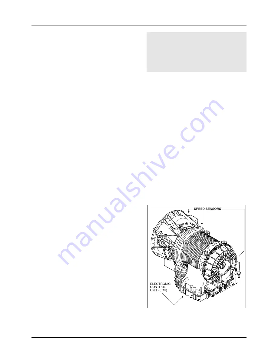
World Transmission
Electronic Control
System
The WT Electronic Control System consists of
five major components connected by wiring har-
nesses:
• Electronic Control Unit (ECU),
• Direct electronic communication from engine
Electronic Control Module (ECM),
• Three speed sensors,
• Push-button shifter,
• Control module which contains solenoid
valves and a pressure switch.
07020


