Other
Features
117
Adjust Acoustic Sensor Timing
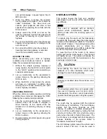
1. Support a flat sheet of cardboard, or similar
material, directly beneath TWS module at a
distance of 4½ feet below module. Sheet
must be facing sensors.
NOTE
Before proceeding, visually inspect sensors to
verify that they are pointing directly at floor, or
nearly, and are not pointing off at an extreme
angle.
CHECKING NORMAL PLATFORM POSITION
23372
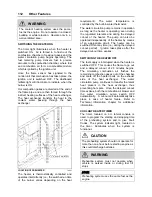
2. Note the sensor timing access hole. This
hole provides access to a plunger-actuated
switch that sets the sensor timing. Insert a
1/16-inch diameter wire-like object into the
access hole and press the plunger inward.
The LED will flash momentarily while the
module establishes the distance and then
remain on steady. Release the plunger
when the LED ceases to flash.
NOTE
It is important that objects, such as your body,
tools, seats, etc, do not interfere with the
beam while the adjustment is being made.
INTERIOR APPOINTMENTS
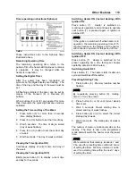
To accommodate a wheelchair, two rows of
regular seats on one side of the coach must be
folded and slid away. Seats may be folded on
both sides of the coach to make room for a
second wheelchair.
POSSIBLE SEATING ARRANGEMENTS
23259
An electrical wheelchair or tri-wheeler may
require sliding back seats from both sides of the
coach to allow enough turnaround space.
1
2
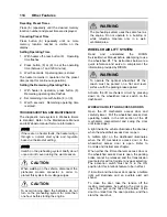
FOLDING SEATS
18430
To fold a set of seats, raise the seat back then
lift up the seat cushion (pull on lever 1). To slide
a row of seats, remove the black covers from
the floor tracks. Pull the lever 2 while sliding the
seat along the track.
The wheelchair occupants have a hostess/stop
chime and a reading light switch at their disposal
on the window sill of the coach, within easy
reach.
Wheelchair Restraint System
Two sets of wheelchair restraint belts are kept in
plastic pouches and stowed in an overhead
compartment.
To secure each wheelchair, four tiedown straps
must be used (at all four corners).
Summary of Contents for X3-45 2011
Page 1: ...COACH MANUFACTURER OPERATOR S MANUAL X3 45 COACH PA1581...
Page 4: ......
Page 6: ......
Page 10: ......
Page 24: ......
Page 128: ......
Page 134: ......
Page 171: ...Technical Information 165 X3 45 OVERALL DIMENSIONS SIDE ELEVATION 18673...
Page 172: ...Technical Information 166 X3 45 OVERALL DIMENSIONS TOP FRONT AND REAR VIEWS 18674...
Page 182: ......
Page 186: ......
Page 206: ......


