Other Features
120
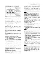
Use one person on each side of the lift to
prevent mechanical binding.
With fingers up and palms forward, push the
platform forcefully to start the lift moving inward.
As the lift begins to move inward, maintain a
constant pushing motion until the lift comes to
rest completely inside the lift enclosure.
Push firmly and make sure that the platform
manual release shafts have turned to lock the
platform.
To manually stow the lift from ground level
In the unlikely event of a hydraulic system failure
and the manual backup pump is inoperative, the
lift may be stowed as follows by
two or more
able-bodied people
:
Raise or lower the platform to the deploy/stow
position; the platform frame must be parallel to
the side of the lift enclosure. If the exact position
cannot be obtained. Slightly low is preferred to
slightly high.
Using the rollstop manual control knob and one
hand on the rollstop, close the rollstop until it
latches.
WARNING
The platform is heavy and should be lifted
using caution and proper lifting technique:
Always lift with legs and not the back when
attempting to lift heavy objects.
Use one person on each side of the lift to
prevent mechanical binding.
With fingers up and palms forward, push the
platform forcefully to start the lift moving inward.
As the lift begins to move inward, maintain a
constant pushing motion until the lift comes to
rest completely inside the lift enclosure.
Push firmly and make sure that the platform
manual release shafts have turned to lock the
platform.
WHEELCHAIR LIFT REMOVAL FOR
STORING OR MAINTENANCE PURPOSES
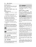
Disconnect connector located at compartment
ceiling.
Remove 4 fixing bolts located inside
compartment, on each side of platform.
Grasp the platform and pull firmly, sustaining a
constant pull so that the platform slides onto the
rails until the carriage come in contact with the
stops.
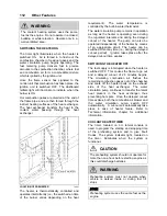
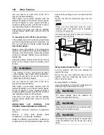
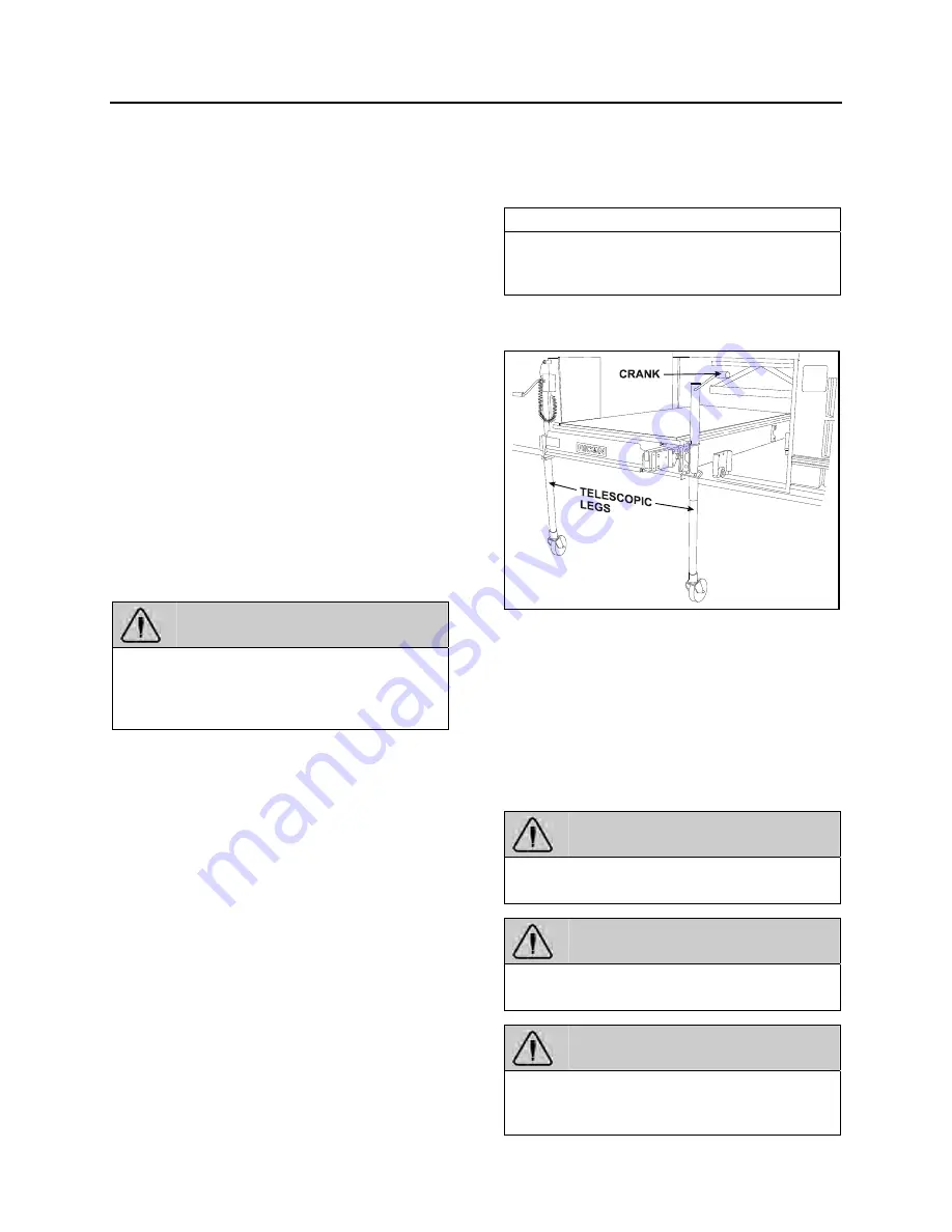
Secure the first two telescopic legs onto the
platform.
NOTE
There are two telescopic legs for each
platform side. The proper side is indicated
onto the telescopic leg.
Turn telescopic leg crank to raise the carriage to
be able to clear the stops.
INSTALLATION OF TELESCOPIC LEGS
23333
Pull the platform until the rear carriage hit
against the stops.
Secure the two rear telescopic legs onto the
platform then turn telescopic leg crank to be
able to clear the stops.
Remove platform completely.
Lower the platform to minimum height using the
telescopic leg cranks before moving it.
WARNING
For better stability, keep the platform at
minimum height when moving.
WARNING
Never deploy the platform from enclosure while
standing on the telescopic legs.
WARNING
Telescopic legs were designed to support and
move the platform only, do not use as a work
table.
Summary of Contents for X3-45 2011
Page 1: ...COACH MANUFACTURER OPERATOR S MANUAL X3 45 COACH PA1581...
Page 4: ......
Page 6: ......
Page 10: ......
Page 24: ......
Page 128: ......
Page 134: ......
Page 171: ...Technical Information 165 X3 45 OVERALL DIMENSIONS SIDE ELEVATION 18673...
Page 172: ...Technical Information 166 X3 45 OVERALL DIMENSIONS TOP FRONT AND REAR VIEWS 18674...
Page 182: ......
Page 186: ......
Page 206: ......

