Safety Features and Equipment
137
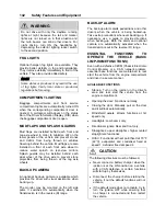
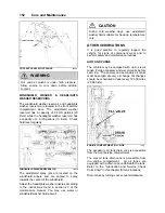
WARNING REFLECTORS
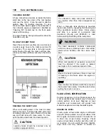
A kit containing three triangular reflectors is
provided to warn other drivers on the road in
case of a breakdown. The kit is located at the
ceiling of the first baggage compartment, on the
R.H. side. The reflectors provide visible warning
of an emergency situation. The three reflectors
should be placed as indicated on the box cover.
These reflectors comply with FMVSS
125
(Federal Motor Vehicle Safety Standards).
WARNING REFLECTORS LOCATION
23376
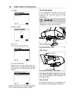
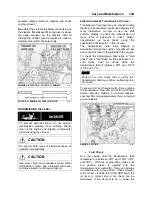
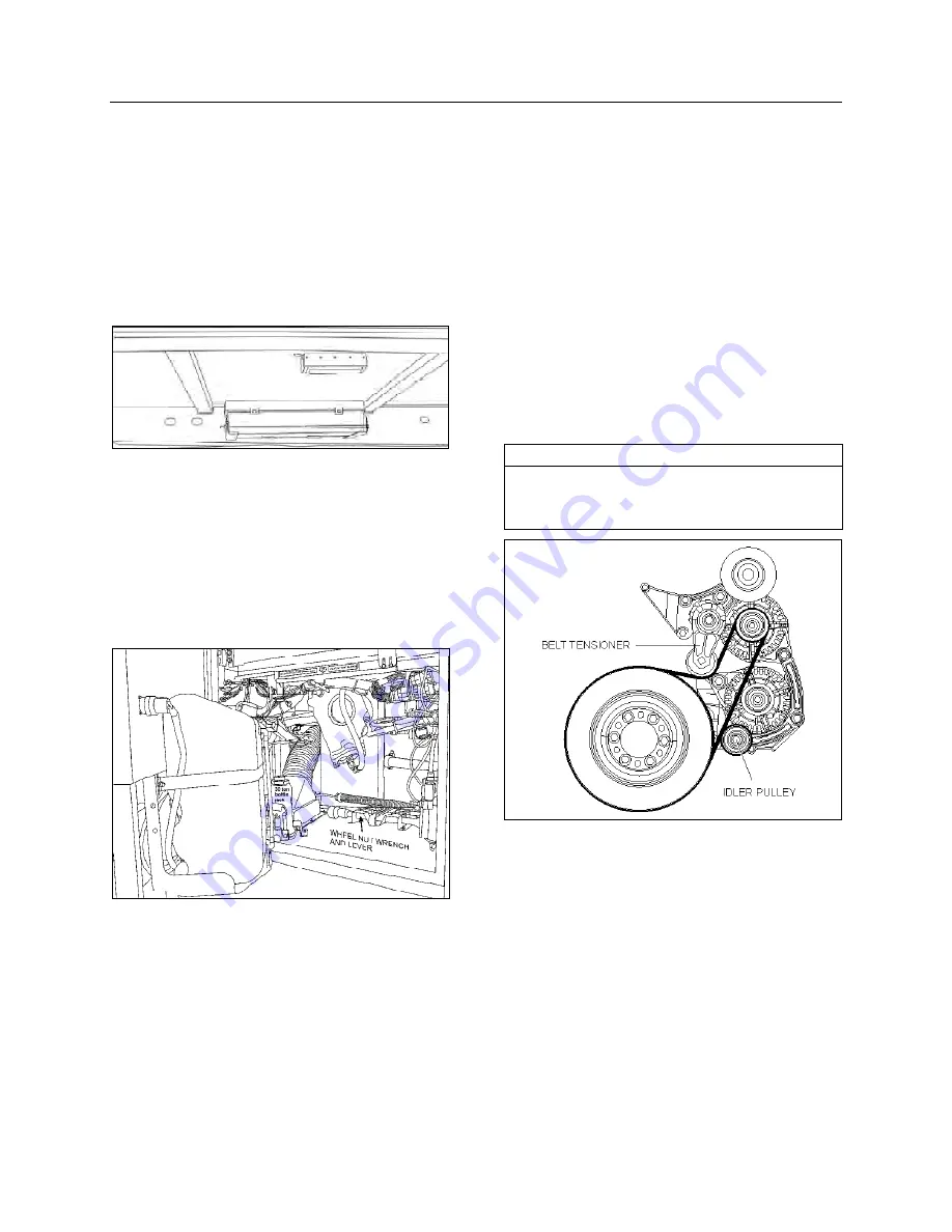
JACK / TOOLS
A kit for jacking up the vehicle and changing
wheels is stored in the front service
compartment. The kit includes a:
•
30 ton bottle jack;
•
Wheel nut wrench and lever.
JACK/TOOLS LOCATION
23377
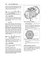
SPARE PARTS KIT
The vehicle may be equipped with a spare parts
kit (optional). The kit contains parts such as
bulbs, circuit breakers, belts, etc. The spare
parts kit is stored in the first baggage
compartment.
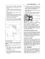
“LIMP-HOME” BELT
In case of malfunction of the lower alternator,
install the limp-home belt on the upper
alternator. The installation of the belt allows the
coach to be driven to a repair facility after only
minor manipulations.
Lower alternator failure:
1. Raise the belt tensioner. Use a breaker bar
with a ¾ inch drive to rotate the tensioner
pulley upward and relieve alternator belt
tension. Remove belt;
2. Install the limp-home drive belt on the drive
and top alternator pulleys first;
3. Complete installation of the limp-home belt
as shown hereafter;
4. Slide the belt on the idler pulley;
5. Gently release the belt tensioner.
NOTE
To prevent the batteries from discharging, the
HVAC system is turned OFF when running on
a single alternator.
LIMP-HOME BELT ON TOP ALTERNATOR
01194
SPARE WHEEL AND TIRE
The spare wheel and tire is located in a
compartment behind the reclining front bumper.
In case of a flat tire, turn ON the hazard flashers
and bring the coach to a stop on the side of the
road. Apply the parking brake. Make sure the
coach is parked safely away from traffic. Set up
the triangular reflectors in accordance with
applicable highway regulations.
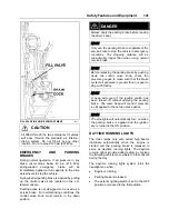
CHANGING A WHEEL
To access the spare wheel, lower the front
bumper. To remove the spare, untighten the
Summary of Contents for X3-45 2011
Page 1: ...COACH MANUFACTURER OPERATOR S MANUAL X3 45 COACH PA1581...
Page 4: ......
Page 6: ......
Page 10: ......
Page 24: ......
Page 128: ......
Page 134: ......
Page 171: ...Technical Information 165 X3 45 OVERALL DIMENSIONS SIDE ELEVATION 18673...
Page 172: ...Technical Information 166 X3 45 OVERALL DIMENSIONS TOP FRONT AND REAR VIEWS 18674...
Page 182: ......
Page 186: ......
Page 206: ......


