Safety Features and Equipment
138
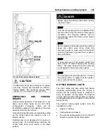
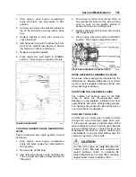
pressure screw holding the tire in place, then
press down on the spring loaded locking pin
located at the top of the retaining bracket and
remove the bracket. Using the strap, pull the
spare out of the compartment (refer to the
following illustrations). Rollers ease
manipulation. Remove the protective cover.
Install the flat tire in place of the spare by
reversing the procedure.
NOTE
Do not forget to have the flat tire repaired as
soon as possible.
SPARE WHEEL AND TIRE
18415
1. Loosen the wheel nuts about one turn;
2. Raise the vehicle by the closest jacking
point (See Jacking Points in this chapter);
3. Remove the wheel nuts and remove the
wheel;
4. Mount the spare wheel over the studs, being
careful not to damage the stud threads;
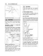
5. Screw in the wheel nuts according to the
sequence shown in the following figure and
tighten slightly more and repeat the
sequence a few times to position the wheel
correctly. Once tightening induces wheel
spin, lower the coach for final tightening;
6. Tighten the nuts progressively in the
sequence shown. Final tightening should be
done using a torque wrench. Dry tightening
torque is 450 – 500 lbf-ft (610 – 680 Nm) for
steel as well as for aluminum wheels.
TIGHTENING SEQUENCE
13018
NOTE
The jack and tools are located in the front
service compartment.
NOTE
Periodically check the spare’s inflation
pressure. Tire pressure should be the
maximum pressure specified in the chart.
NOTE
Periodically check that the spare is securely
fastened in its compartment.
WARNING
Before driving, be sure the flat tire, track, jack
and tools are securely reinstalled in their
respective compartments. Check that the
bumper is securely closed shut before driving.
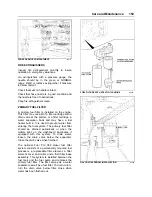
JACKING POINTS
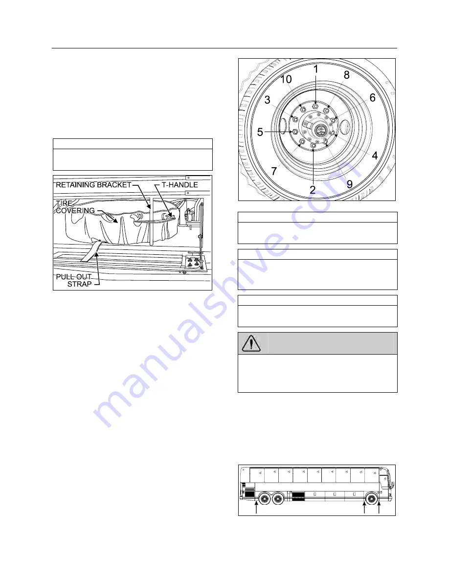
Twelve jacking points are located on the vehicle;
three are located on each side of the frame and
two are located under each axle. Refer to the
following illustrations for the location of jacking
points.
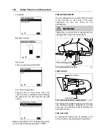
JACKING POINTS ON FRAME
18618
Summary of Contents for X3-45 2011
Page 1: ...COACH MANUFACTURER OPERATOR S MANUAL X3 45 COACH PA1581...
Page 4: ......
Page 6: ......
Page 10: ......
Page 24: ......
Page 128: ......
Page 134: ......
Page 171: ...Technical Information 165 X3 45 OVERALL DIMENSIONS SIDE ELEVATION 18673...
Page 172: ...Technical Information 166 X3 45 OVERALL DIMENSIONS TOP FRONT AND REAR VIEWS 18674...
Page 182: ......
Page 186: ......
Page 206: ......


