Care and Maintenance
154
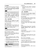
A/C COMPRESSOR BELT TENSION
ADJUSTMENT
The air conditioning compressors are driven by
V-belts.
Belt tensioning is applied through air bellows
which are adjusted by an air pressure regulating
valve mounted in the engine compartment, right
behind the belt tensioning pressure control
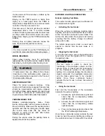
valve. The correct pressure of 45 psi (310 kPa)
is set at the factory. Periodically verify the
pressure at the regulating valve using a
pressure gauge and correct if necessary.
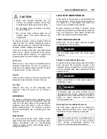
AIR BELLOWS
01069
For belt replacement, air pressure must be
released from bellows by means of the belt
tensioning pressure control valve. This valve,
mounted close to the pressure regulating valve,
is manually operated. Before handling, set the
rear start switch to OFF and observe all
applicable safety precautions.
•
Refer to the Parts Manual, Maintenance
Manual or "Service Bulletins" for
recommended belt sizes and tension
settings;
•
Periodically inspect belt and pulleys for wear
or damage;
•
Do not treat belts with any compounds.
Keep belts dry.
PRESSURE REGULATING VALVE
12200
FAN AND ALTERNATOR DRIVE BELTS
These belts have automatic belt tensioner to
keep the correct tension without adjustment.
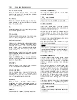
BACK-UP CAMERA
The optional back-up camera is located on the
rear cap. To clean the camera's protective glass,
spray with soapy water. Wipe with a clean damp
rag or wiper blade.
WARNING
To avoid injury, do not clean camera with
transmission in reverse (R). Shut off engine
and apply parking brake before cleaning.
CAUTION
To prevent scratches to the camera protective
glass, do not wipe with dry rag. Use a clean
damp rag.
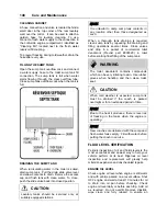
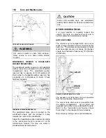
AIR FILTER RESTRICTION INDICATOR
A filter restriction indicator (optional) is used to
monitor the vacuum level between the air filter
and engine. A red marker is displayed when the
air filter is clogged. Replace the air filter when a
red marker is displayed or after a maximum of
two years. Reset by pressing on the indicator's
extremity.
The filter restriction indicator is located on the
engine air intake duct
Summary of Contents for X3-45 2011
Page 1: ...COACH MANUFACTURER OPERATOR S MANUAL X3 45 COACH PA1581...
Page 4: ......
Page 6: ......
Page 10: ......
Page 24: ......
Page 128: ......
Page 134: ......
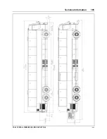
Page 171: ...Technical Information 165 X3 45 OVERALL DIMENSIONS SIDE ELEVATION 18673...
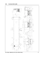
Page 172: ...Technical Information 166 X3 45 OVERALL DIMENSIONS TOP FRONT AND REAR VIEWS 18674...
Page 182: ......
Page 186: ......
Page 206: ......


