Technical
Information
169
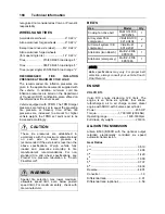
VOLVO I-SHIFT TRANSMISSION
Technologically advanced twelve speed
automated mechanical transmission
Gear Ratios
1
st
................................................................14.94
2
nd
...............................................................11.73
3
rd
.................................................................9.04
4
th
.................................................................7.09
5
th
.................................................................5.54
6
th
.................................................................4.35
7
th
.................................................................3.44
8
th
.................................................................2.70
9
th
.................................................................2.08
10
th
...............................................................1.63
11
th
...............................................................1.27
12
th
...............................................................1.00
Reverse 1
st
.................................................17.48
Reverse 2
nd
............................................... 13.73
Differential ratio ............................................2.50
Maximum input torque..... 1850 Lb-Ft (2500 Nm)
PROPELLER SHAFT
Hayes-Dana SPL250 type tubular shafts. It is
provided with heavy-duty universal joints.
BRAKES
The features of the braking system include a
dual system where the front and rear circuits are
completely independent from each other. The
brakes are air operated disc type brakes with
automatic slack adjusters on front, drive and tag
axles. The emergency/parking brakes are
located on the drive and tag axles only.
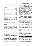
BRAKE CHAMBER EFFECTIVE AREA
Front axle .................................................. 24 in
2
Drive axle ..........24/24 in
2
(service / emergency)
Tag axle.............14/16 in
2
(service / emergency)
AIR SYSTEM
Compressed air is provided by a twin cylinder,
31.8 cfm Wabco, gear-driven, water-cooled and
engine oil lubricated air compressor.
ANTILOCK BRAKING SYSTEM (ABS)
The antilock braking system has one Electronic
Control Unit (ECU) controlling a four channel
system. A wheel slip sensor is mounted at each
front axle and drive axle wheel. The Tag axle
wheels are slave to the drive axle wheels.
The Electronic Control Module (ECM) is
maintenance free. Its operating voltage is 24 ±
6 volts DC. The thermal operating range for the
ECM is from -40 to 167°F (-40 to 75°C).
The solenoid control valves are maintenance
free. Their operating voltage is 24 (+4.8, -2.4)
volts DC. The rated current draw is 1.65 amps.
The thermal operating range of the solenoid
control valves is from -40 to 176°F (-40 to 80°C).
TROUBLESHOOTING AND TESTING
For troubleshooting and testing of the vehicle's
anti-lock braking system, refer to Meritor
WABCO Maintenance Manual:
“Anti-Lock Brake
Systems For Trucks, Tractors and Buses"
or use
dashboard Driver Information Display (DID).
AUTOMATIC TRACTION CONTROL
(ATC) – ELECTRONIC STABILITY
PROGRAM (ESP)
In addition to the ABS function, vehicle may be
equipped with an advanced model of Bendix
EC-60 controller to provide an
Automatic
Traction Control (ATC)
feature. Bendix ATC
can improve vehicle traction during acceleration,
and lateral stability while accelerating through
curves. ATC utilizes
Engine Torque Limiting
(ETL)
where the ECU communicates with the
engine’s controller and/or
Differential Braking
(DB)
where individual wheel brake applications
are used to improve vehicle traction.
The EC-60 advanced model controller also
provides ABS-based stability features referred to
as
ESP
Electronic Stability Program
.
Refer to Maintenance Manual, Section 12: Brake
and Air System for more information on this
system.
CAUTION
Even with ESP-equipped vehicles, the driver
remains responsible for ensuring vehicle
stability during operation.
DANGER
ESP may reduce the vehicle speed
automatically
.
ESP can make the vehicle
decelerate
automatically.
ESP can slow the vehicle with
or
without the operator applying the brake,
and
even when the throttle is being applied.
Summary of Contents for X3-45 2011
Page 1: ...COACH MANUFACTURER OPERATOR S MANUAL X3 45 COACH PA1581...
Page 4: ......
Page 6: ......
Page 10: ......
Page 24: ......
Page 128: ......
Page 134: ......
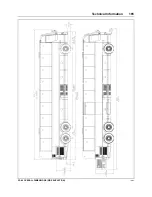
Page 171: ...Technical Information 165 X3 45 OVERALL DIMENSIONS SIDE ELEVATION 18673...
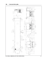
Page 172: ...Technical Information 166 X3 45 OVERALL DIMENSIONS TOP FRONT AND REAR VIEWS 18674...
Page 182: ......
Page 186: ......
Page 206: ......

