Appendix B - Troubleshooting Guide for Multiplex Vehicles
183
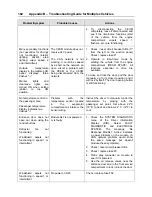
Problem/Symptom
Probable Causes
Actions
HVAC condenser fans not
functioning in speed 1
Circuit breaker CB7 was
manually tripped and not
reset
Check / reset circuit breaker CB7
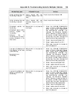
HVAC condenser fans not
functioning in speed 2
Circuit breaker CB7 was
manually tripped and not
reset
Check / reset circuit breaker CB7
Windshield washer not
functioning
Windshield upper section
de-icing system not
functioning
Defroster fan is
functioning but no heat or
cooling available in the
driver area.
Module A46 is not powered
or is faulty
1. Check the SYSTEM DIAGNOSTIC
menu of Driver Information Display
(DID). Select FAULT DIAGNOSTIC
and ELECTRICAL SYSTEM. The
message “No Response ModA46,
Active” indicates a power problem on
the module. (A CAN network problem
would show the same message but
doesn't produce these symptoms).
2. Check / reset circuit breaker CB1
3. Check / replace fuse F12 or F13
4. Probe gray connector on module to
see if it is powered.
Low beam headlights and
front flasher on left side
not functioning
Electric horn not
functioning
Module A45 is not powered
or is faulty
1. Check the SYSTEM DIAGNOSTIC
menu of Driver Information Display
(DID). Select FAULT DIAGNOSTIC
and ELECTRICAL SYSTEM. The
message “No Response ModA45,
Active” indicates a power problem on
the module. (A CAN network problem
would show the same message but
doesn't produce these symptoms).
2. Check / reset circuit breaker CB2
3. Check / replace fuse F33 and F34
4. Probe gray connector on module to
see if it is powered.
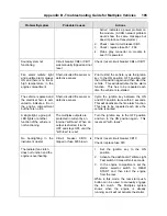
Low beam headlights and
flasher on right side not
functioning
Module A48 is not powered
or is faulty
1. Check the SYSTEM DIAGNOSTIC
menu of Driver Information Display
(DID). Select FAULT DIAGNOSTIC
and ELECTRICAL SYSTEM. The
message “No Response ModA48,
Active” indicates a power problem on
the module. (A CAN network problem
would show the same message but
doesn't produce these symptoms).
2. Check / reset circuit breaker CB2
3. Check / replace fuse F33 and F34
4. Probe gray connector on module to
see if it is powered.
Summary of Contents for X3-45 2011
Page 1: ...COACH MANUFACTURER OPERATOR S MANUAL X3 45 COACH PA1581...
Page 4: ......
Page 6: ......
Page 10: ......
Page 24: ......
Page 128: ......
Page 134: ......
Page 171: ...Technical Information 165 X3 45 OVERALL DIMENSIONS SIDE ELEVATION 18673...
Page 172: ...Technical Information 166 X3 45 OVERALL DIMENSIONS TOP FRONT AND REAR VIEWS 18674...
Page 182: ......
Page 186: ......
Page 206: ......

