background image

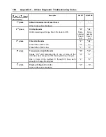
Appendix C – Allison Diagnostic Troubleshooting Codes


194 

DTC 

Description 

CHECK 

TRANS 

Light 

Inhibited Operation 

Description 

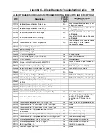
P2793  Gear Shift Direction Circuit 

Yes 

Ignores PWM input from shift 
selector 

P2808  Pressure Control Solenoid 6 (PCS6) Stuck Off 

Yes 

DNS, RPR 

P2809  Pressure Control Solenoid 6 (PCS6) Stuck On 

Yes 

DNS, RPR 

P2812  Pressure Control Solenoid 6 (PCS6) Control Circuit Open 

Yes 

DNS, SOL OFF (hydraulic default) 

P2813  Pressure Control Solenoid (PCS) 6 System Performance 


P2814  Pressure Control Solenoid 6 (PCS6) Control Circuit Low 

Yes 

DNS, SOL OFF (hydraulic default) 

P2815  Pressure Control Solenoid 6 (PCS6) Control Circuit High 

Yes 

DNS, SOL OFF (hydraulic default) 

U0001  Hi Speed CAN Bus Reset Counter Overrun (IESCAN) 

No 

Use default values, inhibit SEM 

U0010  CAN BUS Reset Counter Overrun 

No 

Use default values, inhibit SEM 

U0100  Lost Communications with ECM/PCM (J1587) 

Yes 

Use default values 

U0103 

Lost Communication with Gear Shift Module  
(Shift Selector) 1 

Yes 

Maintain range selected, observe 
gear shift direction circuit 

U0115  Lost Communication with ECM 

Yes 

Use default values 

U0291 

Lost Communication with Gear Shift Module  
(Shift Selector) 2 

Yes 

Maintain range selected, observe 
gear shift direction circuit 

U0304  Incompatible Gear Shift Module 1 (Shift Selector) ID 

Yes 

Ignore shift selector inputs 

U0333  Incompatible Gear Shift Module 2 (Shift Selector) ID 

Yes 

Ignore shift selector inputs 

U0404 

Invalid Data Received From Gear Shift Module  
(Shift Selector) 1 

Yes 

Maintain range selected, observe 
gear shift direction circuit 

U0592 

Invalid Data Received From Gear Shift Module  
(Shift Selector) 2 

Yes 

Maintain range selected, observe 
gear shift direction circuit 


Summary of Contents for X3-45 2011

Page 1: ...COACH MANUFACTURER OPERATOR S MANUAL X3 45 COACH PA1581...

Page 2: ...PA1581 1 ST Edition Date January 2011 Starting from vehicle A 9926 B 9965 B 9971 B 9992 B 5002 Featuring EPA 2010...

Page 3: ...this manual in the coach at all times Make sure this manual is kept with the coach when ownership is transferred Please use the appropriate card at the end of this manual to promptly notify Prevost o...

Page 4: ......

Page 5: ...123 SAFETY FEATURES AND EQUIPMENT 129 CARE AND MAINTENANCE 143 TECHNICAL INFORMATION 163 ABBREVIATIONS 175 APPENDIX A SERVICE LITERATURE 177 APPENDIX B TROUBLESHOOTING GUIDE FOR MULTIPLEX VEHICLES 18...

Page 6: ......

Page 7: ...Safety Precautions 1 SAFE OPERATING PRACTICES 2 DEFENSIVE DRIVING PRACTICES 2 OTHER PRECAUTIONS 3...

Page 8: ...gine before refueling adding oil performing maintenance or servicing tasks unless stated otherwise Fuel is highly flammable and explosive Do not smoke when refueling Keep away from open flames or spar...

Page 9: ...sure even if all tanks are empty Before performing any work on the vehicle refer to wiring diagrams and or air schematics to thoroughly understand the system CAUTION Disconnect all electronic control...

Page 10: ......

Page 11: ...9 CONDENSER COMPARTMENT A C 10 EVAPORATOR COMPARTMENT 10 COOLANT HEATER COMPARTMENT 11 FRONT ELECTRICAL AND SERVICE COMPARTMENT 11 BAGGAGE COMPARTMENTS 12 SPARE WHEEL COMPARTMENT 13 FUEL AND DIESEL EX...

Page 12: ...Condenser compartment 7 Entrance door control switch 8 Entrance door 9 Engine compartment rear doors 10 Rear view mirrors 11 Spare wheel compartment 12 Front electrical and service compartment 13 Driv...

Page 13: ...cap 4 Coolant fluid surge tank sight glass 5 Air filter restriction indicator 6 Engine oil dipstick 7 Belt tensioner control valve 8 Starter selector switch and Engine rear start push button switch En...

Page 14: ...ed unlocked using the central locking system by pressing the switch located on the L H side dashboard panel ENGINE COMPARTMENT R H SIDE 18607 A telltale light illuminates when one or more compartments...

Page 15: ...ngine door must be open before opening the exhaust aftertreatment system access door To open the access door lower the latch release lever using a flat tip screwdriver To close the door lower the door...

Page 16: ...latch located inside the adjacent baggage compartment to open the condenser door The condenser compartment provides access to the following Diesel Exhaust Fluid DEF Tank Condenser Condenser fans and m...

Page 17: ...rator compartment door COOLANT HEATER COMPARTMENT The water recirculating pump is also located in the engine coolant heater compartment FRONT ELECTRICAL AND SERVICE COMPARTMENT To open the front elect...

Page 18: ...storage capacity The compartments can be locked or unlocked by using the exterior compartment key Pull up operating handle to release the latch and then pull the door open Pressurized cylinders assis...

Page 19: ...artment since they can interfere with the steering linkage mechanism Pull the release handle located inside front service compartment to tilt down the entire bumper assembly RELEASE HANDLE 18613 SPARE...

Page 20: ...on the door lock lever is visible the door is unlocked ENTRANCE DOOR EXTERIOR SWITCH 18599 From the inside open the door by pressing the door opening switch L H button on the R H dashboard panel Clos...

Page 21: ...operating the optional wheelchair lift WHEELCHAIR ACCESS DOOR OPERATING HANDLE 18616 REAR VIEW MIRRORS The vehicle is equipped with flat type and convex type rear view mirrors Convex mirrors give a wi...

Page 22: ...urb side drive axle wheel hub The odometer calculates the total distance in miles or kilometers depending on model installed traveled by the coach since manufacture including factory road testing NOTE...

Page 23: ...ss of attachments or distortion or failure which could affect the safe towing of trailer 3 The ball and trailer coupling should meet the following minimum test load requirements without incurring fail...

Page 24: ......

Page 25: ...PNEUMATIC ISRI SEAT 22 SAFETY BELTS 23 TOUR GUIDE SEAT 24 MICROPHONE JACKS 24 PASSENGER SEATS 24 SWIVEL SEATS 24 FOLDING TRAYS 24 CARD TABLES 25 QUICK LOUNGE SYSTEM 25 OVERHEAD CONSOLE 25 ADJUSTABLE A...

Page 26: ...her utility compartment is located on the console and includes a 12 volt appliance socket UTILITY COMPARTMENT IN CONSOLE 18669 UTILITY COMPARTMENTS 18602 STEERING WHEEL ADJUSTMENT Push on the valve bu...

Page 27: ...iving vehicle as this could result in loss of vehicle control DANGER Make sure that seat is adjusted and that safety belt is buckled up before diving vehicle MECHANICAL ISRI SEAT Adjustment Seat can b...

Page 28: ...ce Lumbar Support To inflate the upper lumbar support bellows depress the front rocker switch 7 upward To deflate depress the rocker switch downward Follow the same procedure to inflate and deflate th...

Page 29: ...ration becomes defective report to maintenance personnel immediately FASTENING SEATBELT 18028 NOTE The safety belt must be pulled out slowly and continuously otherwise it will lock the reel before the...

Page 30: ...holders and footrests PASSENGER SEAT EQUIPMENT 18121A All seats are track mounted so that the seating configuration can be changed Each set is mounted on rectangular aluminum bases to make cleaning be...

Page 31: ...h on the locking clamp to release the leg Unfold the leg until the clamp locks it in position CARD TABLE INSTALLATION 23146 QUICK LOUNGE SYSTEM Quick Lounge is a quick fit modular system providing lux...

Page 32: ...ated on the dashboard refer to Controls Instruments chapter will activate the reading light circuit and allow passenger control of reading lights WINDOWS The coach is equipped with frameless flush mou...

Page 33: ...E SUNSHADE 23019 VENTILATION HATCH A ventilation hatch may be installed in the ceiling at the rear of the coach A second optional hatch can be installed on the roof at the front of the coach To open t...

Page 34: ...partment located over the mirror A liquid soap dispenser and moist towel dispenser are optional Locking the lavatory door from the inside will illuminate a fluorescent light in the lavatory and two ou...

Page 35: ...R 36 ASHTRAY 37 UTILITY COMPARTMENT 37 12 VOLT APPLIANCES SOCKET 37 TRAILER AIR SUPPLY CONTROL VALVE 37 EMERGENCY PARKING BRAKES OVERRULE CONTROL VALVE 37 BACK UP CAMERA AND MONITOR 37 SCENIC VIEWING...

Page 36: ...AL 80 ACCELERATOR PEDAL 81 ALLISON AUTOMATIC TRANSMISSION 81 OPERATION 81 PUSHBUTTON SHIFT SELECTOR 81 MODE 81 TRANSMISSION SERVICE INDICATOR 82 DESCRIPTION OF AVAILABLE RANGES 82 VOLVO I SHIFT TRANSM...

Page 37: ...LAVATORY DOOR KEY Use this key to lock or unlock the lavatory UTILITY AND VIDEO COMPARTMENT KEY Use this key to lock or unlock the lockable utility compartments and the lockable overhead compartment c...

Page 38: ...trance door and Message Center Display MCD Maintain the switch in this position when parked overnight or for an extended period NOTE The battery master switch is on when the hazard flashers are activa...

Page 39: ...ophone 3 DOT certification plate 4 Diagnostic Data Reader DDR receptacle 5 Foot operated steering wheel adjustment unlock air valve 6 Driver s utility compartment 7 Dashboard 8 Rear view monitor optio...

Page 40: ...l pad 2 Control switches 3 Mirror controls 4 Tag axle control valve 5 Parking brakes control valve 6 Coolant heater timer option 7 Low buoy control valve option 8 Cigarette Lighter option 9 Ashtray op...

Page 41: ...brakes must be applied to allow the use of the kneeling Kneeling Full Hi Buoy Optional 0 6251 Momentarily press the rocker switch downwards to lower the front end of the coach 4 inches 100mm Momentari...

Page 42: ...LVES 12129 PARKING BRAKES CONTROL VALVE 5 Spring loaded parking brakes are applied by pulling up the control valve knob and protector assembly Lift the safety cover and push down to release brakes Ref...

Page 43: ...tor is mounted on the windshield L H side pillar and switches ON automatically when the transmission is in the reverse R range SCENIC VIEWING SYSTEM CAMERA The optional scenic viewing system enables t...

Page 44: ...vehicle at a desired cruising speed To turn off the system press the rocker switch to the off position NOTE The CRUISE switch and RESUME button do not operate at speeds below 30 mph 50 km h CRUISE CO...

Page 45: ...ake will provide low braking power or high braking power depending on which of the two steering wheel engine brake control buttons is activated engine brake low engine brake high The transmission reta...

Page 46: ...lar cruise control activation Press the CRUISE rocker switch to the ON position accelerate the vehicle to the desired cruising speed and then press the SET button ACB is now engaged with the set follo...

Page 47: ...t the radar sensor mounting and remove any obstruction that may impair the sensor functioning Driver warnings Before using the ACB the driver should fully understand all the audible and visual warning...

Page 48: ...potential collision The Impact Alert is also applicable to stationary metallic objects such as stopped or stalled vehicles This alert provides a warning given up to 3 0 seconds before a potential coll...

Page 49: ...tationary metallic object in your lane of travel On the dashboard the Forward Vehicle Detected telltale flashes in red Impact Alert pop up message appears on the DID The speedometer LEDs flash in red...

Page 50: ...E pictogram For proper functioning of the system the radar must be perfectly aligned and not blocked If a radar fault condition is detected one of the following pop up messages will show in the DID AC...

Page 51: ...ve been received by the display SPARE TIRE PRESSURE DEVIATIONS TARGET PRESSURES GAUGE PRESSURES 1 1 SPARE TIRE PRESSURE DEVIATIONS TARGET PRESSURES GAUGE PRESSURES PSI PSI As illustrated the pressure...

Page 52: ...rm the display switches automatically to temperature readings The driver can also press any of the menu keys to momentary switch the display to temperature readings In this case the temperature readin...

Page 53: ...are received and the readings are blinking if not within the optimum pressure range From this point the user can scroll through the menus to get more detailed information and inflate deflate the tires...

Page 54: ...Instrument Cluster 3 Vehicle Clearance Information 4 R H Dashboard Panel 5 HVAC Control Unit 6 Audio video Selector Panel VSS 05 7 AM FM CD Radio 8 Air Vents 9 Brightness Control 10 Diver Information...

Page 55: ...he operation of the coach it also includes the ignition switch and an adjustable air vent L H DASHBOARD PANEL 06762 06254 Headlights and Exterior Lighting Off position Daytime running lights only Pres...

Page 56: ...This may damage the washer fluid pumps Windshield Upper Section De icing 06259 The coach is equipped with a de icing system in the windshield upper section Press the rocker switch to activate the blo...

Page 57: ...ion will deactivate the auto mode and the eco roll mode will not be available NOTE On vehicles equipped with the I Shift transmission any increase of the braking power such as from auto mode to engine...

Page 58: ...utomatically as speed gets below 5 mph Over a prolonged period this situation will increase tire wear and stress to the vehicle O Do not engage during downhill operation R H DASHBOARD PANEL The HVAC c...

Page 59: ...s This switch powers the reading light circuit enabling passengers to operate their personal reading lights Refer to Coach Interior chapter 06245 Passenger Overhead Air Registers Press the switch to t...

Page 60: ...closed To prevent battery run down the central A C and heating systems will not operate if the charging system is not working properly When the A C system is running park at least 4 feet 1 5 m from o...

Page 61: ...sender unit failure the coolant valve will remain open and three lines will be displayed WARNING Warm temperatures may cause drowsiness and affect alertness while driving Keep the temperature comfort...

Page 62: ...s after selecting BASS TREB BAL and LOUD modes the unit automatically sets in the VOL mode The volume value adjust from 0 com plete mute to 40 maximum SELECTION OF AUDIO OR AUDIO VIDEO SOURCE Press RA...

Page 63: ...ally saves the setting and exits this mode GONG SOUND LEVEL A gong will sound in the passenger s area upon activating of the microphone This gong will also sound when a passenger activates the service...

Page 64: ...adio Manual tuning down 3 Menu button Radio Push and release to access menu 4 Fast forward button Radio Seek CD USB Push and release to select next track CD USB Push and hold for fast forward Bluetoot...

Page 65: ...lect and play audio files stored on the iPod via the radio menus It is not possible to transfer audio from the iPod to the radio solely by the USB port A connection via the AUX port will be necessary...

Page 66: ...the Driver Information Display DID Indications and warnings are presented according to three levels of attention required 1 THE TELLTALE LIGHTS The highest level of attention The telltale lights are t...

Page 67: ...th AWARE Adaptive Cruise Braking ACB system Refer to Prevost AWARE Adaptive Cruise Braking paragraph Turbo Boost Pressure Psi 06730 Indicates the turbo boost pressure in psi This pressure should be th...

Page 68: ...ight is on can ultimately result in automatic engine shutdown and loss of power steering assist Vehicle crash can occur resulting in severe personal injuries Front Brake Air Pression Psi 06737 Indicat...

Page 69: ...ure is low DEF Level 06735 Indicates the amount of DEF diesel exhaust fluid remaining in the DEF tank The DEF tank is considered as being full when it contains 16 gallons 60 liters of DEF DEF consumpt...

Page 70: ...y applying more braking power and or steering clear of the vehicle ahead to avoid a potential collision RED System malfunction The Adaptive Cruise Braking is not available INFORMATION This telltale li...

Page 71: ...required soon Refer to Exhaust Aftertreatment System paragraph in Other Features chapter LOW DEF LEVEL 06740_C Illuminates when there is less than 2 6 gallons 10 liters of DEF left in the tank CAUTION...

Page 72: ...4 mph 7 km h the indicator will remain illuminated until the coach reaches that speed Refer to Other Features chapter TRAILER ANTILOCK BRAKE SYSTEM ABS 06740_I Illuminates when the trailer ABS is not...

Page 73: ...ngine will gradually reduce power output to 50 This telltale light always activates an audible alarm After the automatic engine shutdown sequence the engine may be restarted after the key is turned of...

Page 74: ...osition transmission I Shift are part of the default display You can replace the default display by your selection of favorite gauges using the Driver Information Display sub menu Favorite Display Set...

Page 75: ...field or to cancel a setting or operation 06743 Scrolling through the menus without using the steering wheel buttons In case of failure of the steering wheel buttons it is still possible to gain acces...

Page 76: ...Description Engine oil temperature Outside air temperature A C A c compressor pressure This pictogram is displayed with A C compressor suction pressure value low side and discharge pressure value hig...

Page 77: ...which can advise that the transmission oil or filter change is necessary Refer to Appendix C for more information on the Allison transmission prognostic features oil life monitor filter life monitor t...

Page 78: ...the DID menus perform a system diagnostic by selecting DIAGNOSTIC VIEW ACTIVE FAULTS ELECTRICAL SYSTEM and see the fault messages NOTE To prevent discharge of the batteries when the engine in not runn...

Page 79: ...gram indicates that the lavatory compartment is occupied This pictogram will appear only when the engine is shut down in order to advise the driver of the presence of a passenger in the lavatory compa...

Page 80: ...er mpg liters hour Leg fuel consumption This pictogram is displayed with the value for the fuel consumption for the current leg Trip data Function of the DID s Time Distance menu Refer to Driver Infor...

Page 81: ...ase of a fire stop the vehicle immediately stop the engine and evacuate the vehicle NOTE It is possible to cancel an alarm while on the road To do so stop the vehicle Cycle the ignition between the ON...

Page 82: ...e Auto Mode available with I Shift transmission Indicates that the engine brake is in the Auto mode When in this mode the engine brake is activated upon pressing of the brake pedal To select the Auto...

Page 83: ...nge maneuver is completed The lever will spring back into the OFF position once released Headlight Beam Toggle Switch 3 Toggle between high and low beams by pulling the lever up towards you To flash t...

Page 84: ...raph in this chapter 5 12 Left Sunshade Right Sunshade Press and hold the button to lower the left or right sunshade Press twice rapidly and hold the button to raise the left or right sunshade CAUTION...

Page 85: ...ed with a transmission retarder this button has the same effect than the Retarder Engine Brake Low button On vehicles equipped with engine brake pressing this button will permit full application of en...

Page 86: ...the more total braking power is provided Refer to OTHER FEATURES chapter for further information about the transmission retarder NOTE If the wheels start to lock up on slippery roads the output retar...

Page 87: ...d the corresponding letter or number is displayed indicating the transmission is ready to operate in the selected range If the transmission control module TCM detects a serious problem in the transmis...

Page 88: ...at startup for a bulb check this indicator will then be turned off if no service conditions exist DESCRIPTION OF AVAILABLE RANGES R Reverse Press the R button to select reverse Com pletely stop the ve...

Page 89: ...will not upshift above the highest gear selected unless engine overspeed is detected 2 Second range Select this range when operating in heavy and congested traffic The transmission will start in firs...

Page 90: ...elector has four gear positions R N D and M R Reverse N Neutral D Drive M Manual program It is not possible to shift neither directly from R position to D or M position nor from D or M position to R p...

Page 91: ...gear displayed in the DID 7 12 will change momentarily to N1 or N2 Eco Roll disengages as soon as the brake pedal or the accelerator pedal is depressed but it remains available To disable Eco Roll se...

Page 92: ...When the vehicle is stopped 1 Apply the parking brake 2 Select the N position on the pushbutton shift selector 3 Turn off the engine STARTING THE VEHICLE UPHILL AND DOWNHILL Hilly Operating Condition...

Page 93: ...ead NOTE When driving in automatic drive mode position D the engine brake control should be in the Auto mode to maximize the integration of the transmission and brake system according to Eco Roll mode...

Page 94: ...R Position The system will select R2 automatically when the pushbutton shift selector is set to R but if wanted the driver can select R1 as reverse gear manually using the button During reverse it is...

Page 95: ...ATIONARY MODE MENUS 101 DISPLAY SETTINGS 101 DIAGNOSTICS 103 PRE TRIP ASSISTANT 104 DATA LOG 105 AFTERTREATMENT 106 PASSWORD 107 TRANSMISSION RETARDER 107 ENGINE BRAKE 107 EXHAUST BRAKE 108 VOLVO ENGI...

Page 96: ...ING AND MAINTENANCE 114 WHEELCHAIR LIFT SYSTEM 114 WHEELCHAIR LIFT AND ACCESS DOORS 114 OPERATING THE WHEELCHAIR LIFT 115 THRESHOLD WARNING SYSTEM TWS ADJUSTMENT 116 INTERIOR APPOINTMENTS 117 EMERGENC...

Page 97: ...on is necessary when the engine internal combustion process alone does not generate enough heat A dosing system injects a mist of diesel fuel into the exhaust system to increase and maintain the after...

Page 98: ...light will illuminate In that situation engine performance is limited Perform a parked regeneration IMMEDIATELY to avoid further derate and prevent from entering into Level 4 LEVEL 4 flashing ATD SERV...

Page 99: ...o level 4 sequence To initiate a stationary regeneration Park the vehicle in a clear area vehicle speed must be 0 mph 0 km h Engine must be on normal idle and fully warmed up coolant temperature above...

Page 100: ...h the skin rinse with plenty of water and remove contaminated clothing If urea solution comes into contact with the eyes rinse for several minutes and call for medical help if necessary If inhaled bre...

Page 101: ...sage DEF TANK NEAR EMPTY ENGINE IN DERATE ADD DEF Gradual engine torque reduction of 25 The DEF tank is empty and the DEF level gauge indicates Empty moreover a diesel fuel refueling is done and the d...

Page 102: ...SL to 5 mph 8 km h The vehicle has to remain stationary before 5 mph 8 km h road speed limit becomes active Conditions to temporarily exit the 5 mph 8 km h road speed limit inducement First engine res...

Page 103: ...l fuel level gauge increases more than 15 approx 34 gallons 130 liters or the vehicle remains stationary speed 0 for 20 min with engine OFF or at idle lighted solid Vehicle road speed limited RSL to 5...

Page 104: ...of Arrival ETA Vehicle Messages Reset Trip Data NON DRIVING STATIONARY MODE MENUS Display Settings 1 Language 2 Units 3 Time Date 4 Favorite Display Setting 5 Display Light 6 Change Password Diagnost...

Page 105: ...ery Voltage Displays the current 12 volts and 24 volts system voltage 8 A C Compressor Pressure Displays the A C compressor suction pressure value LoS low side and discharge pressure value HiS high si...

Page 106: ...estination selection which allows the operator to see the distance to travel before destination Average trip speed is also shown By specifying the distance to your destination the vehicle can calculat...

Page 107: ...vehicle active messages that were previously displayed as pop up messages and then acknowledged When consulting a message the corresponding STOP CHECK or INFORMATION warning light will illuminate Scro...

Page 108: ...d press ENTER button to confirm repeat steps 1 3 to change Gauge 2 and Gauge 3 if needed 5 Display Light The Display Light menu has three sub menus Contrast Adjust the contrast with the UP DOWN button...

Page 109: ...the Esc button to cancel the test Analog gauges The indicators move forwards and backwards between the end positions They do not show any particular value This is just a check to confirm that the indi...

Page 110: ...exterior lighting is functioning properly 2 Air leakage Monitor The Air Leakage check allows the driver to accurately measure the amount of air pressure drop in the front and rear brake air systems Af...

Page 111: ...able information for the trip or leg is Trip distance miles or km Trip fuel average mpg liter 100km km liter Trip fuel used gallons or liters Trip duration on cruise control hours Trip duration with e...

Page 112: ...information about the conditions required for performing regeneration The status can be OK regeneration allowed CHECK regeneration not allowed or N A not applicable When ATS Status is selected the fol...

Page 113: ...the transmission fluid The retarder helps reduce speed on grades without using the vehicle s conventional service braking system This virtually eliminates brake overheating and reduces the risk of a...

Page 114: ...VEB has a higher braking effect than the exhaust brake This engine brake mode is most effective at high engine speeds 1500 to 2300 rpm It is automatically disengaged if engine speed drops below 1000 r...

Page 115: ...bility Program Bendix ATC can improve vehicle traction during acceleration and lateral stability while accelerating through curves ATC utilizes Engine Torque Limiting ETL where the ECU communicates wi...

Page 116: ...ing allowing the DCDL to unlock 3 Resume driving at normal speed using good driving judgment KNEELING SYSTEM This system lowers the front end enabling passengers to get on and off the coach without an...

Page 117: ...ly when the tag axle is in the WHEELS DOWN position Never lower the tag axle while the coach is moving When the tag axle is in the WHEELS UP position the corresponding indicator light will illuminate...

Page 118: ...he regulated intervals and during the delayed cut out of the heater The pump can also be operated independently of the heater by means of an appropriate circuit The heater can be switched ON at any ti...

Page 119: ...tant Heating With Ignition ON Press button 7 Heater is switched on continuous operation and continues to operate until button 7 is pressed again or ignition is switched off NOTE If the ignition is swi...

Page 120: ...e engine Do not operate in a building or while refueling Operate only in a well ventilated area WHEELCHAIR LIFT SYSTEM Read and understand the RICON Service Owner Manual before attempting to use the w...

Page 121: ...ating the lift be careful the control wire doesn t bind with the lift mechanism Using the handheld control pendant deploy the lift by pressing on the DEPLOY button When the lift begins to deploy it is...

Page 122: ...light on the control device illuminates If wheelchair and passenger are detected by acoustic sensors the LED will flash the buzzer will sound and the module red light will flash If this occurs it is...

Page 123: ...rfere with the beam while the adjustment is being made INTERIOR APPOINTMENTS To accommodate a wheelchair two rows of regular seats on one side of the coach must be folded and slid away Seats may be fo...

Page 124: ...rub against sharp edges Do not bleach or dry clean Wheelchair Occupant Restraint Secure the wheelchair occupant in the following manner WHEELCHAIR RESTRAINTS AND ACCESSORIES 23262 Snap the lap belts...

Page 125: ...ocket and pump to raise the platform to the vehicle floor level WHEELCHAIR LIFT MANUAL HYDRAULIC PUMP 23373 The lift passenger and attendant must follow the instructions to ENTER or EXIT the vehicle a...

Page 126: ...start the lift moving inward As the lift begins to move inward maintain a constant pushing motion until the lift comes to rest completely inside the lift enclosure Push firmly and make sure that the p...

Page 127: ...the platform until the front carriage clears the stops Lower the front of the platform Remove the two front telescopic legs from the platform Push firmly and make sure that the platform manual release...

Page 128: ......

Page 129: ...TARTING FROM THE DRIVER S SEAT 124 STARTING FROM THE ENGINE COMPARTMENT 124 COLD WEATHER STARTING 125 JUMP STARTING 125 ENGINE BLOCK HEATER 127 ENGINE WARM UP 127 ALLISON TRANSMISSION WARM UP 127 I SH...

Page 130: ...at normal idle for two minutes to allow lubricating oil to reach the turbocharger then run the engine at fast idle Let oil pressure reach normal operating range before driving NOTE If engine does not...

Page 131: ...heater telltale has turned off before starting the engine If necessary once the engine has started the preheater will reengage post heating for the same length of time as the preheat time WARNING Do n...

Page 132: ...ooster vehicle which produces comparable amperage as your vehicle To jump start proceed as follows 1 Remove the protective cap from the booster block terminal located in the R H side engine compartmen...

Page 133: ...ed DANGER Never let the engine run in an enclosed non ventilated area Engine exhaust fumes contain dangerous gases which can be fatal if inhaled Before warming up the engine open the door s or move th...

Page 134: ......

Page 135: ...WARNING REFLECTORS 137 JACK AND TOOLS 137 SPARE PARTS KIT 137 LIMP HOME BELT 137 SPARE WHEEL AND TIRE 137 CHANGING A WHEEL 137 JACKING POINTS 138 HYDRAULIC JACK 139 TOWING 140 EMERGENCY AIR FILL VALV...

Page 136: ...bottom of the window outwards as illustrated below The window is hinged from the top and will not fall out A telltale light on the dashboard illuminates when a window is opened Refer to Controls and...

Page 137: ...ection of the arrows and push or pull the door open To close the door after emergency opening return the valve to its initial position open the door using the door cylinder then close the door normall...

Page 138: ...y cause an obscuring cloud behind and near the vehicle 5 The red fire ALARM lamp and audible alarm will stay on The yellow fire TROUBLE lamp will also be on indicating a discharged extinguisher 6 The...

Page 139: ...starting point for the learning The user can select another axle with move the cursor to the wheel number with the right arrow and select another wheel with the or move the cursor down to the start le...

Page 140: ...ther operation or unloaded operation The end user can readjust the target pressure within 30 and 20 of the factory set target pressure but not outside this range The factory set target pressure is alw...

Page 141: ...ture settings The cursor can be moved to highlight the number beside new value ACCEPT or EXIT allows increasing or decreasing the numbers Pressure alarms changes are allowed in steps of 1 PSI in the r...

Page 142: ...ated under the seats in the first row on each side of the aisle Instructions for use are found on the extinguishers WARNING Make sure you know how to operate the fire extinguishers in case of an emerg...

Page 143: ...limp home belt on the upper alternator The installation of the belt allows the coach to be driven to a repair facility after only minor manipulations Lower alternator failure 1 Raise the belt tensione...

Page 144: ...d repeat the sequence a few times to position the wheel correctly Once tightening induces wheel spin lower the coach for final tightening 6 Tighten the nuts progressively in the sequence shown Final t...

Page 145: ...e tag axle must be used for raising the tag axle only Several kinds of hydraulic jacks can be used Only jack at the specified jacking points Jack must support the following capacities Front axle 20 00...

Page 146: ...rrectly after towing Tighten axle shaft and driveshaft nuts to the correct torque settings Do not invert shafts CAUTION To prevent damage to the drive train components disconnect axle shafts or drives...

Page 147: ...y conditions The stopping distance will be considerably longer than when using normal service brake NOTE Before releasing the parking brake by pushing down the control valve knob check the pressure ga...

Page 148: ...backing up The monitor may be mounted on the left side pillar It switches ON automatically when the transmission is in the reverse R range BACK UP ALARM The back up alarm alerts pedestrians and other...

Page 149: ...OIL LEVEL 149 POWER STEERING FLUID LEVEL 150 COOLING FAN RIGHT ANGLE GEARBOX OIL LEVEL 151 DRIVE AXLE WHEEL BEARING OIL LEVEL 151 FRONT AND TAG AXLE WHEEL HUBS 151 COOLANT FLUID LEVEL 151 WINDSHIELD W...

Page 150: ...ance 144 PARKING BRAKE TEST 157 EXTERIOR LIGHTING VERIFICATION 157 FIRST SERVICE ON NEW VEHICLE 158 ENGINE OIL 158 COOLANT SYSTEM STRAINER 158 GENERAL RECOMMENDATIONS 159 WALK AROUND INSPECTION BEFORE...

Page 151: ...tarting at the outer edges of the stain and working in toward the center 3 Blot affected area frequently with a clean dry absorbent cloth to prevent stain rings caused by excess solvent WARNING Use so...

Page 152: ...tain persists CARPET Vacuum carpets regularly to prolong carpet life RUBBER COMPONENTS Use only pure water or glycerin to clean stains on rubber components CAUTION Never use solvents on rubber compone...

Page 153: ...er blades loosen them before removing Remove and clean wiper blades periodically with an alcohol based cleaning solution Clean wiper blades using a sponge or soft cloth LAVATORY MAINTENANCE Flush wate...

Page 154: ...a thorough tank draining is required clean sump tank by repeating the draining and filling operations several times Close valves and drop in a packet of commercial toilet deodorant Prevost part 900329...

Page 155: ...ransmission oil level refer to Appendix C under Allison transmission oil level check using the pushbutton shift selector in this manual The transmission fluid level dipstick is accessible through the...

Page 156: ...SION FLUID LEVEL DIPSTICK TYPICAL 07049 Replace dipstick and tighten the filler tube cap until the rubber seal is correctly seated CAUTION Do not overfill transmission fluid reservoir Severe damage ma...

Page 157: ...d screw the side and top filler plugs back in 6 Place engine rear start switch to NORMAL position Close engine compartment door RIGHT ANGLE GEARBOX OIL LEVEL CHECK 05118 DRIVE AXLE WHEEL BEARING OIL L...

Page 158: ...nce manual You may use water or windshield washer fluid as well CAUTION During cold weather days use windshield washer fluid suitable for freezing temperature only OTHER VERIFICATIONS It is good pract...

Page 159: ...ay have a fuel heater built in It is used to prevent water from entering the fuel system The primary fuel filter should be drained periodically or when the telltale light on the dashboard illuminates...

Page 160: ...n settings Periodically inspect belt and pulleys for wear or damage Do not treat belts with any compounds Keep belts dry PRESSURE REGULATING VALVE 12200 FAN AND ALTERNATOR DRIVE BELTS These belts have...

Page 161: ...ole To gain access to the A C filters unscrew the grill located at the top step of the entrance door steps Remove the filters for cleaning or replacement NOTE If the windshield is continuously fogged...

Page 162: ...eduled maintenance For heavy loads or extended use lubricate more often Refer to the Maintenance Manual section 24 for information on lubrication WHEELS AND TIRES Check for loose wheel nuts Inspect al...

Page 163: ...w air pressure to reach 95 psi 655 kPa before releasing parking brake Driving the vehicle while the parking brake is applied should not be possible EXTERIOR LIGHTING VERIFICATION Exterior Lighting Tes...

Page 164: ...e engine is running do this quick enough so that the engine does not stop Go to the right side of the vehicle same sequence as left side FIRST SERVICE ON NEW VEHICLE NOTE Refer to Maintenance Manual f...

Page 165: ...enger seats In case of fire immediately evacuate all occupants Occupant safety is the first priority Do not attempt to extinguish the fire if there is immediate danger or risk for personal injury When...

Page 166: ...Care and Maintenance 160 COMPONENTS IDENTIFICATION COMPONENTS REPRESENTATION MAY DIFFER SLIGHTLY FROM AN ACTUAL VEHICLE...

Page 167: ...in place Check windshield and headlights washer reservoir fluid level and add if necessary Step 2 Front of the Coach Check for damage and clean if dirty Check windshield wiper arms for proper spring...

Page 168: ...ant surge tank fluid level add if necessary Check air cleaner restriction indicator replace air cleaner when red signal locks in full view Check stop light tail light directional signal light and back...

Page 169: ...CK BRAKING SYSTEM ABS 169 TROUBLESHOOTING AND TESTING 169 AUTOMATIC TRACTION CONTROL ATC ELECTRONIC STABILITY PROGRAM ESP 169 STEERING 170 ELECTRICAL SYSTEM 170 SUSPENSION 170 I BEAM AXLE FRONT SUSPEN...

Page 170: ...Technical Information 164 PLATES AND CERTIFICATION 173 SAFETY CERTIFICATION 174 DOT CERTIFICATION PLATE 174 VEHICLE IDENTIFICATION NUMBER VIN 174 COACH FINAL RECORD 174...

Page 171: ...Technical Information 165 X3 45 OVERALL DIMENSIONS SIDE ELEVATION 18673...

Page 172: ...Technical Information 166 X3 45 OVERALL DIMENSIONS TOP FRONT AND REAR VIEWS 18674...

Page 173: ...U S qts 15 l Differential oil 20 U S qts 18 7 l Power steering reservoir 4 0 U S qts 3 8 l A C compressor oil 4 5 U S qts 4 3 l Windshield washer reservoir 5 3 U S gal 20 l Refrigerant 24 1 lb 11 kg F...

Page 174: ...e specifications Weigh vehicle fully loaded and pressurize according to tire manufacturer s recommendations For non standard tire and wheel specifications see Prevost tire pressure tabulation in Coach...

Page 175: ...ECM is from 40 to 167 F 40 to 75 C The solenoid control valves are maintenance free Their operating voltage is 24 4 8 2 4 volts DC The rated current draw is 1 65 amps The thermal operating range of t...

Page 176: ...BEAM AXLE FRONT SUSPENSION OPTION 2 Bellows 12 for a G A W R of 16 500 lb 2 Shock absorbers 4 Radius rods 1 Transverse radius rod 1 Height control valve 1 sway bar 1 diameter INDEPENDENT FRONT SUSPENS...

Page 177: ...to 5 microns Shut off valve on fuel supply line Provided with filling access on the right side of the coach EXHAUST SYSTEM One all stainless steel exhaust aftertreatment system including Catalylic co...

Page 178: ...ash engine oils will reduce the cleaning interval on the Diesel Particulate Filter DPF DPF regenerates the combustible soot but the ash a product of the oil lubricant package slowly accumulates in the...

Page 179: ...t lb kg 41 88 19 PLATES AND CERTIFICATION The main components of the vehicle such as engine transmission axles and chassis are identified by different serial numbers It may be necessary to locate thes...

Page 180: ...sure is also etched on this plate The DOT Certification plate is affixed to L H control panel DOT CERTIFICATION PLATE 00016 VEHICLE IDENTIFICATION NUMBER VIN VEHICLE IDENTIFICATION NUMBER 00044 The Ve...

Page 181: ...ispositif lectronique de contr le de la stabilit E Eco Roll FAP Filtre Particules Diesel Particulate Filter DPF FDA Following Distance Alert Alerte de distance FED Fluide d chappement Diesel Diesel ex...

Page 182: ......

Page 183: ...E LITERATURE 178 NOTICE 179 DECLARATION OF THE MANUFACTURING DEFECTS TO THE GOVERNMENT OF THE UNITED STATES 179 DECLARATION OF THE MANUFACTURING DEFECTS TO THE CANADIAN GOVERNMENT 179 DECLARATION OF T...

Page 184: ...rvice literature are available on request and at low cost These can be helpful to mechanics and drivers alike Maintenance Manual Operator s Manual Parts Manual Service Center Directory To order call P...

Page 185: ...ar Inc To contact NHTSA you may either call the Auto Safety Hotline toll free at 1 800 424 9393 or 366 0123 in Washington D C area or write to NHTSA U S Department of transportation Washington D C 205...

Page 186: ......

Page 187: ...use F65 d Probe gray connector on module to see if it is powered 2 Verify that the engine ECM is powered and get the ignition signal a Check reset circuit breaker CB8 Check replace fuse F74 b Check re...

Page 188: ...e door manually up to its closed position and it will lock by itself The door opening button is still functioning No temperature control in the passenger area Passenger temperature display indicates t...

Page 189: ...e F12 or F13 4 Probe gray connector on module to see if it is powered Low beam headlights and front flasher on left side not functioning Electric horn not functioning Module A45 is not powered or is f...

Page 190: ...ECTRICAL SYSTEM The message No Response ModA52 Active indicates a power problem on the module A CAN network problem would show the same message but doesn t produce this symptom 2 Check reset circuit b...

Page 191: ...Short circuited fire sensor or defective sensor Cycle the ignition key between the ON and OFF position twice within 3 seconds This will deactivate the fire alarm function This has to be repeated each...

Page 192: ...press a second time to engage in 2nd speed press a third time to stop the fan press once again to return to 1st speed If the fan clutch does not engage using this procedure then the clutch is faulty o...

Page 193: ...OLS 188 DIAGNOSTIC CODE DISPLAY AND CLEARING PROCEDURE ALLISON 4 TH GENERATION CONTROLS 189 DIAGNOSTIC CODE RESPONSE 190 ALLISON TRANSMISSION DIAGNOSTIC TROUBLESHOOTING CODES DTC AND DESCRIPTIONS 191...

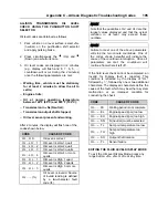
Page 194: ...ult from a previous malfunction The TCM may automatically delete a code from memory if it has not recurred If the condition which generated the code is active the LED indicator on the selector will be...

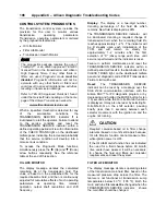
Page 195: ...isplay for code d1 3 Press the MODE button to see the next code d2 repeat for subsequent codes d3 d4 d5 NOTE Be sure to record all codes displayed before they are cleared This is essential for trouble...

Page 196: ...IC CODE RESPONSE The following responses are used in the Diagnostic Troubleshooting Code List and Inhibited Operation Description table to command safe operation when diagnostic codes are sent DNS Do...

Page 197: ...alues P063F Auto Configuration Engine Coolant Temp Input Not Present No None P0658 Actuator Supply Voltage 1 HSD1 Low Yes DNS SOL OFF hydraulic default P0659 Actuator Supply Voltage 1 HSD1 High Yes DN...

Page 198: ...ansmission Pressure Switch 2 Circuit Low P0848 Transmission Pressure Switch 2 Circuit High P088A Transmission Fluid Filter Deteriorated P088B Transmission Fluid Filter Very Deteriorated P0880 TCM Powe...

Page 199: ...4 PCS4 Control Circuit Open Yes DNS SOL OFF hydraulic default P2719 Pressure Control Solenoid PCS 4 System Performance P2720 Pressure Control Solenoid 4 PCS4 Control Circuit Low Yes DNS SOL OFF hydra...

Page 200: ...lt values inhibit SEM U0010 CAN BUS Reset Counter Overrun No Use default values inhibit SEM U0100 Lost Communications with ECM PCM J1587 Yes Use default values U0103 Lost Communication with Gear Shift...

Page 201: ...Oil Level is HIgh 2 quarts O L H I 3 Oil Level is HIgh 3 or more quarts O L fc Oil Level is invalid Source of invalid reading is defined by a two character fault code fc NOTE Note that the quantities...

Page 202: ...shaft revolutions and shift frequency Display The display is a two digit number denoting percentage of the fluid life which remains New fluid is displayed as 99 The TRANSMISSION SERVICE indicator will...

Page 203: ...lso be reset by selecting N R N R N D N on the shift selector pausing briefly less than 3 seconds between each selector movement with the ignition on and the engine not running TRANSMISSION HEALTH MON...

Page 204: ...99 down to 00 Some number from 9 to 0 Some number from 9 to 0 Filter Life Monitor F M Present life of filter is OK O K 3rd press Present life of filter is low L O Transmission Health Monitor O K Shows...

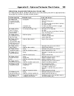
Page 205: ...05 Flame detector Wiring Defective flame detector Damaged wiring open or short circuit Replace flame detector 6X Flashes F 06 Temperature sensor Wiring Defective temperature sensor Damaged wiring ope...

Page 206: ......
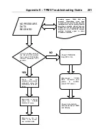
Page 207: ...problem Antennas power is short circuited or defective Cycle the ignition between the ON and OFF position then check if TPMS telltale indicator illuminates for 3 seconds Reprogram a sensor using the...

Page 208: ...has not been reprogrammed into the display Wheels have been installed without sensors One of the antennas is defective or not properly connected Check that all antennas are properly connected using th...

Page 209: ...E TPMS TROUBLESHOOTING GUIDE 201 AUTOMATIC FIRE DETECTION AND SUPPRESSION SYSTEM AFSS 37 AUTOMATIC TRACTION CONTROL ATC ELECTRONIC STABILITY PROGRAM ESP 109 169 B BACK UP ALARM 142 BACK UP CAMERA AND...

Page 210: ...22 SAFETY BELTS 23 DRIVER INFORMATION DISPLAY DID MENUS 98 DRIVING MODE MENU 98 FUEL DATA 100 GAUGES 98 RESET TRIP DATA 101 TIME DISTANCE 100 VEHICLE MESSAGES 101 E ELECTRICAL SYSTEM 170 ELECTRONIC DE...

Page 211: ...AXLE WHEEL BEARING OIL LEVEL 151 ENGINE OIL LEVEL 148 FRONT AND TAG AXLE WHEEL HUBS 151 POWER STEERING FLUID LEVEL 150 TRANSMISSION OIL LEVEL 149 WINDSHIELD WASHER HEADLIGHTS WASHER RESERVOIR 152 FOG...

Page 212: ...47 LAVATORY 28 LOW BUOY 111 M MICROPHONE JACKS 24 MUD FLAPS AND SPLASH GUARDS 142 N NON DRIVING STATIONARY MODE MENUS 101 AFTERTREATMENT 106 DATA LOG 105 DIAGNOSTICS 103 DISPLAY SETTINGS 101 PASSWORDS...

Page 213: ...MN CONTROLS 77 HORNS 79 MULTI FUNCTION LEVER 77 STEERING WHEEL CONTROLS 78 TRANSMISSION RETARDER 80 STEERING WHEEL ADJUSTMENT 20 STEERING 170 SUSPENSION 170 DRIVE AXLE 170 I BEAM AXLE FRONT SUSPENSION...

Page 214: ...Index 208 OR MAINTENANCE PURPOSES 120 WHEELS AND TIRES 168 RECOMMENDED TIRE INFLATION PRESSURE AT MAXIMUM COLD LOAD 168 WINDOWS 26 DRIVER S POWER WINDOW 27 PANORAMIC WINDOWS 26...

Reviews:

Related manuals for X3-45 2011