Coach Interior
20
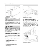
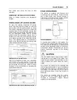
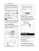
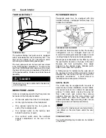
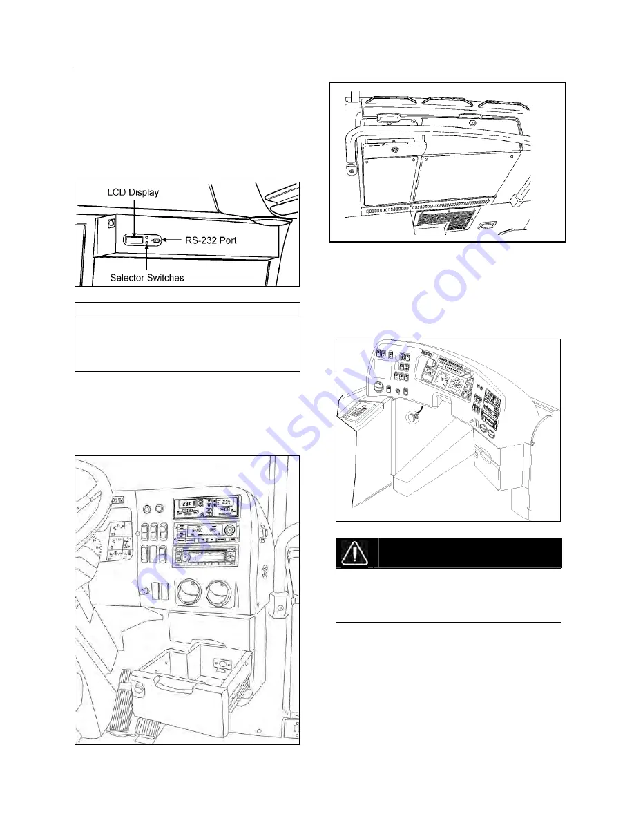
ELECTRONIC DESTINATION SIGN
Turn the optional destination sign lighting on and
off using the rocker switch located on the
dashboard. Refer to Controls & Instruments
chapter.
Depress the selecting switches until the desired
destination appears in the Liquid Crystal Display.
ELECTRONIC DESTINATION SIGN
23123
NOTE
The destination sign must be programmed with
a computer connected to the RS-232 connector
prior to first use. Follow the instructions on the
computer disk to install and run the software.
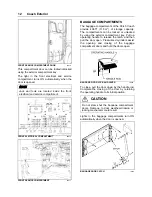
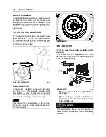
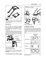
UTILITY COMPARTMENTS
Two lockable utility compartments are located at
the base of the windshield. Another utility
compartment is located on the console, and
includes a 12 volt appliance socket.
UTILITY COMPARTMENT IN CONSOLE
18669
UTILITY COMPARTMENTS
18602
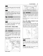
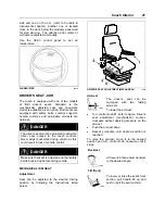
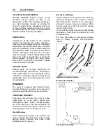
STEERING WHEEL ADJUSTMENT
Push on the valve button located in the foot-
operated control housing to unlock the steering
wheel for tilt and telescopic adjustment (refer to
“Controls and Instruments“ chapter).
TILT AND TELESCOPIC ADJUSTMENT
18670
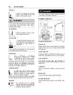
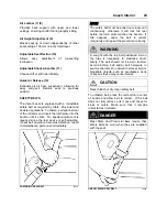
DANGER
Do not adjust the steering wheel while driving.
Loss of control could result. Park the vehicle
safely and apply parking brakes before
adjusting the steering wheel.
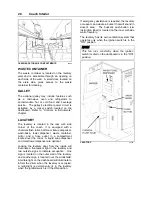
AISLE MIRROR
A central mirror allows the driver to see in the
aisle. Adjust mirror manually.
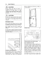
ADJUSTABLE HVAC REGISTERS
The HVAC system has adjustable registers to
control air flow around the driver’s area. Three
are located on the dashboard; two on the R.H.
Summary of Contents for X3-45 2011
Page 1: ...COACH MANUFACTURER OPERATOR S MANUAL X3 45 COACH PA1581...
Page 4: ......
Page 6: ......
Page 10: ......
Page 24: ......
Page 128: ......
Page 134: ......
Page 171: ...Technical Information 165 X3 45 OVERALL DIMENSIONS SIDE ELEVATION 18673...
Page 172: ...Technical Information 166 X3 45 OVERALL DIMENSIONS TOP FRONT AND REAR VIEWS 18674...
Page 182: ......
Page 186: ......
Page 206: ......

