Section 06: ELECTRICAL
PA1593
10
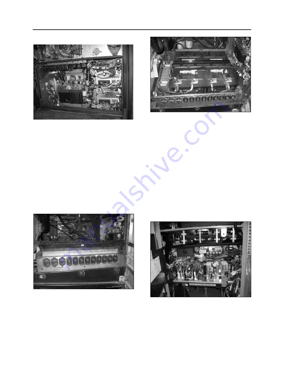
2.3 REAR
ELECTRICAL PANEL
FIGURE 7: REAR ELECTRICAL PANEL
The rear electrical panel provides access to the
following:
Rear terminal block;
Multiplex
modules;
Vehicle Electrical Center Rear (VECR)
Relays and fuses;
Transmission
TCM;
Battery master switch (Master cut-out);
Diagnostic Data Reader (DDR) receptacle,
(refer to “Other Features” chapter).
2.4
REAR JUNCTION PANEL
FIGURE 8: REAR ELECTRICAL JUNCTION PANEL
06634
2.5 BATTERY
COMPARTMENT
The Battery Compartment provides access to
the batteries (2), battery equalizer and master
relay (R1).
FIGURE 9: BATTERY COMPARTMENT
2.6 FRONT ELECTRICAL AND SERVICE
COMPARTMENT
The front electrical and service compartment is
located on L.H. side of vehicle, under the
driver's window. It contains the following
components (Fig. 10):
Front terminal block;
Master Chassis Module (MCM);
Vehicle Electrical Center Front (VECF) and
Multiplex Modules;
Relays and fuses;
ABS Electronic Control Unit (ECU);
Common Powertrain Controller (CPC);
VECU with Volvo D13 engine;
FIGURE 10: FRONT ELECTRICAL COMPARTMENT
06673
2.7
A/C JUNCTION BOX
The A/C junction box is located inside the
evaporator compartment on the X3-45 coach.
Summary of Contents for X3-45 2016
Page 4: ......
Page 16: ...Section 00 GENERAL INFORMATION PA1593 12 FIGURE 12 METRIC US STANDARD CONVERSION TABLE 00005...
Page 17: ...Section 00 GENERAL INFORMATION 13 PA1593 FIGURE 13 CONVERSION CHART 00006...
Page 18: ......
Page 26: ......
Page 58: ......
Page 72: ...Section 04 EXHAUST AND AFTERTREATMENT SYSTEM PA1593 14 7 TORQUE SPECIFICATIONS...
Page 73: ...SECTION 04 EXHAUST AND AFTERTREATMENT SYSTEM PA1593 15...
Page 74: ...Section 04 EXHAUST AND AFTERTREATMENT SYSTEM PA1593 16...
Page 76: ......
Page 96: ......
Page 134: ......
Page 176: ...SECTION 06B ELECTRICAL 38 overcurrent working Circuit 306 shorted to ground...
Page 180: ......
Page 202: ......
Page 205: ...Section 09 PROPELLER SHAFT PA1593 3 FIGURE 1 PROPELLER SHAFT ASSEMBLY 09002...
Page 256: ......
Page 268: ......
Page 295: ...SECTION 16 SUSPENSION PA1593 9 2 5 TORQUE SPECIFICATIONS...
Page 296: ...Section 16 SUSPENSION PA1593 10...
Page 297: ...Section 16 SUSPENSION PA1593 11...
Page 314: ......
Page 380: ......
Page 388: ......
Page 413: ...Section 22 HEATING AND AIR CONDITIONING PA1593 15 FIGURE 18 REFRIGERANT CIRCUIT CENTRAL SYSTEM...
Page 433: ...Section 22 HEATING AND AIR CONDITIONING PA1593 35 FIGURE 36 CENTRAL HEATING SYSTEM COMPONENTS...


