Section 06: ELECTRICAL
PA1593
12
DANGER
All lead-acid batteries generate hydrogen gas,
which is highly flammable. If ignited by a spark
or flame, the gas may explode violently,
causing spraying of acid, fragmentation of the
battery, which may result in severe personal
injuries. Wear safety glasses and do not
smoke when working near batteries. In case of
contact with acid, flush immediately with
water.
The battery has four (4) major functions:
1. Providing a source of current for starting the
engine;
2. Stabilizing the voltage in the electrical
system;
3. Supplying current for a limited time, when
electrical demands of the equipment exceed
the power output of the alternator;
4. Providing a limited source of power for
connected accessories, when the engine is
not running.
3.1
BATTERY DISCHARGE PROTECTION
To prevent discharge of the batteries when the
engine in not running, certain functions are
automatically switched off if the battery voltage
drops below 24 volts for more than 30 seconds.
The "BATTERY VOLTAGE WARNING"
pictogram will show on the DID. Set the ignition
key to the OFF position and then turn the
ignition key to the ON position to reactivate
these functions for a period of 30 seconds
before they switch off again.
If a prolonged use of the functions with the
engine not running is necessary, connect the
battery to a charger.
3.2
MAIN BATTERY RELAYS
Main battery (master) relays (12V and 24V) are
provided for this vehicle. The relays are located
in the battery compartment and on the rear
electrical panel. The 24-volt battery relay (R1)
engages when ignition switch is in the ON or
ACC position and battery master switch (master
cut-out) is turned ON.
When the main battery relays (R1 & R3) are
tripped to the
OFF
position, all electrical supply
from the batteries is cut off, with the exception of
the following items.
Battery equalizer check module;
MCM;
TCM (World transmission);
ECM (Engine Control Module),
Water recirculating pump;
Bi-fold entrance door;
Cluster
memory.
3.3
BATTERY REMOVAL AND
INSTALLATION
The batteries are located in the battery
compartment on the R.H. side of the engine
compartment and are accessible from the
engine compartment curb-side door.
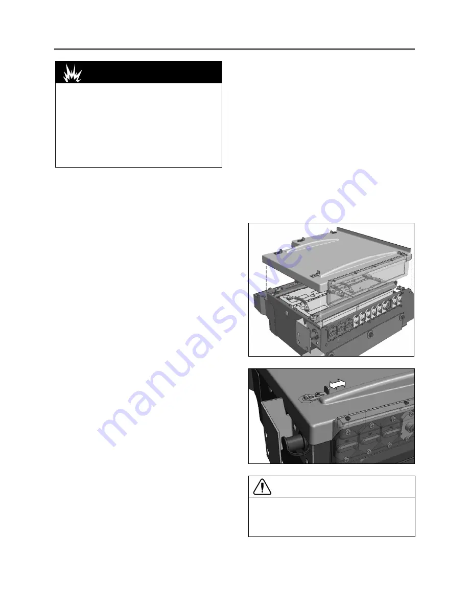
1. Remove or put aside the battery compartment
protective cover (Fig. 14 & 15).
FIGURE 14: BATTERY PROTECTIVE COVER
FIGURE 15: LATCH ON PROTECTIVE COVER
CAUTION
To protect battery terminals and circuit
breaker bus bars against mist and corrosion,
make sure that the battery protective cover is
properly fitted and latched (five latches).
Summary of Contents for X3-45 2016
Page 4: ......
Page 16: ...Section 00 GENERAL INFORMATION PA1593 12 FIGURE 12 METRIC US STANDARD CONVERSION TABLE 00005...
Page 17: ...Section 00 GENERAL INFORMATION 13 PA1593 FIGURE 13 CONVERSION CHART 00006...
Page 18: ......
Page 26: ......
Page 58: ......
Page 72: ...Section 04 EXHAUST AND AFTERTREATMENT SYSTEM PA1593 14 7 TORQUE SPECIFICATIONS...
Page 73: ...SECTION 04 EXHAUST AND AFTERTREATMENT SYSTEM PA1593 15...
Page 74: ...Section 04 EXHAUST AND AFTERTREATMENT SYSTEM PA1593 16...
Page 76: ......
Page 96: ......
Page 134: ......
Page 176: ...SECTION 06B ELECTRICAL 38 overcurrent working Circuit 306 shorted to ground...
Page 180: ......
Page 202: ......
Page 205: ...Section 09 PROPELLER SHAFT PA1593 3 FIGURE 1 PROPELLER SHAFT ASSEMBLY 09002...
Page 256: ......
Page 268: ......
Page 295: ...SECTION 16 SUSPENSION PA1593 9 2 5 TORQUE SPECIFICATIONS...
Page 296: ...Section 16 SUSPENSION PA1593 10...
Page 297: ...Section 16 SUSPENSION PA1593 11...
Page 314: ......
Page 380: ......
Page 388: ......
Page 413: ...Section 22 HEATING AND AIR CONDITIONING PA1593 15 FIGURE 18 REFRIGERANT CIRCUIT CENTRAL SYSTEM...
Page 433: ...Section 22 HEATING AND AIR CONDITIONING PA1593 35 FIGURE 36 CENTRAL HEATING SYSTEM COMPONENTS...


