Section 06: ELECTRICAL
PA1593
18
NOTE
It is of the utmost importance to have a DID
(Driver Information Display) in working
condition because it is the most important tool
to achieve troubleshooting on a multiplex
vehicle.
4.2 PROBING VOLTAGE ON THE
MULTIPLEX CIRCUITS
Some Multiplex modules are supplied by 12
volts while others are supplied by 24 volts. The
12-volt or 24-volt information is found on the
modules symbol in the wiring diagram. Before
taking voltage readings to track the source of a
problem, first verify if the module is supplied by
12V or 24V, if not, residual voltage on the
module inputs/outputs can draw an erroneous
conclusion.
Inactive Multiplex output = Residual voltage of
18% to 33% of supply voltage.
Inactive Multiplex input = Residual voltage of
50% of supply voltage.
NOTE
o
Verify on the wiring diagram whether the
voltage is 12V or 24V,
o
For a 12V module: an active voltage would
be 12V or 0V but not in between. If you
measure the intermediate tensions (ex.
6V, 2V, or 4V) this must be interpreted as
if the input or the output is inactive.
o
For a 24V module: an active voltage would
be 24V or 0V but not in between. If you
measure the intermediate tensions (ex.
12V, 4V, or 8V) this must be interpreted as
if the input or the output is inactive.
4.3 CAN
NETWORK
The CAN network wiring is separated in sections
and uses connectors, with the exception of C27,
that are not shared with other circuits. This
allows sections of the network to be isolated to
help locate short-circuit on the CAN.
In case of a short-circuit on the CAN network,
this affects all the modules and they all act as
“No response” in the error messages of the
“
Electrical System
” menu. To locate a short-
circuit, proceed by disconnecting one module
zone at a time while verifying if this makes
inactive the errors in the modules still
connected. Connector C1 (front electrical &
service compartment) disconnects all the
modules at the rear of the vehicle from the
network. Connector C5 (front electrical & service
compartment) disconnects all the modules from
the entrance door & wiper control panel.
Connector C3 (rear electrical panel) disconnects
all the modules at the rear of the vehicle from
the network.
Example: Disconnect C5 and C1 and then verify the
status of the errors. If the front modules (A41 to A46)
now give inactive errors, which means short-circuit is
elsewhere than in the front electrical & service
compartment.
4.3.1 Spare CAN
A spare CAN network is installed between the
front and the rear of the vehicle. It has
connectors installed at each end to facilitate
swapping from the regular CAN network to the
spare CAN network. Refer to the vehicle wiring
diagram and section 4.6 for more information.
4.4
MULTIPLEX INPUT TEST MODE
The multiplex input test provides useful
information to diagnose multiplexed inputs of
switches and sensors, complimentary to the
electrical system diagnosis.
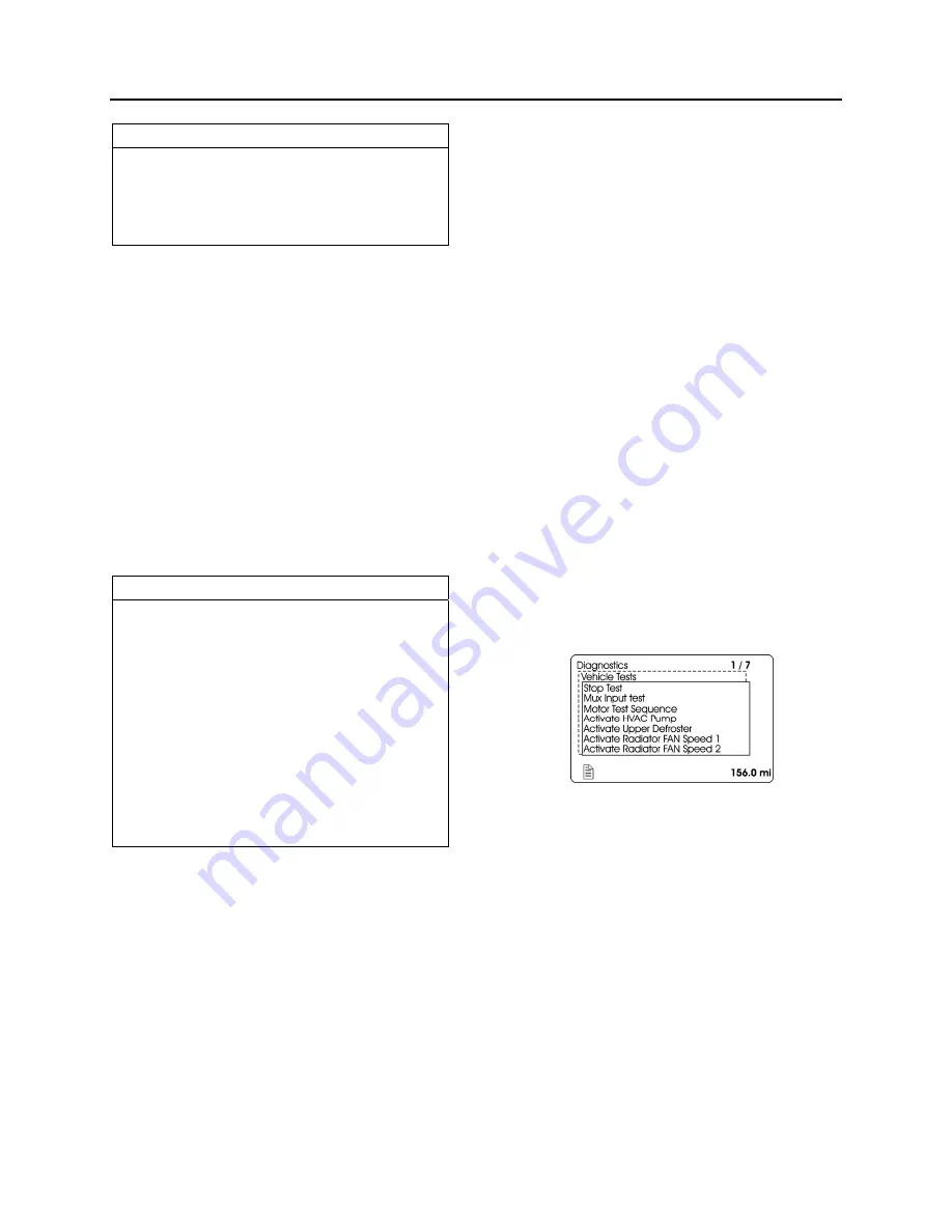
To initiate the test mode, use the Driver
Information Display (DID) DIAGNOSTICS menu.
Select VEHICLE TESTS submenu and then
MUX INPUT TEST. Pres ENTER button to start
the test. The DID status line will show TEST to
confirm the test mode is active. To exit test,
press ESCAPE button, select STOP TEST
submenu and then press ENTER button twice.
TEST will disappear from the DID status line.
Instrument panel audible alarm emits a
beep
each time an OFF/ON transition is detected on a
multiplex input. This allows quick verifying if the
switches and sensors are detected or seen by
the multiplex modules. When the vehicle is
parked, the back-up alarm also emits a
beep
that allows verification of the sensors at the rear
of the vehicle.
Summary of Contents for X3-45 2016
Page 4: ......
Page 16: ...Section 00 GENERAL INFORMATION PA1593 12 FIGURE 12 METRIC US STANDARD CONVERSION TABLE 00005...
Page 17: ...Section 00 GENERAL INFORMATION 13 PA1593 FIGURE 13 CONVERSION CHART 00006...
Page 18: ......
Page 26: ......
Page 58: ......
Page 72: ...Section 04 EXHAUST AND AFTERTREATMENT SYSTEM PA1593 14 7 TORQUE SPECIFICATIONS...
Page 73: ...SECTION 04 EXHAUST AND AFTERTREATMENT SYSTEM PA1593 15...
Page 74: ...Section 04 EXHAUST AND AFTERTREATMENT SYSTEM PA1593 16...
Page 76: ......
Page 96: ......
Page 134: ......
Page 176: ...SECTION 06B ELECTRICAL 38 overcurrent working Circuit 306 shorted to ground...
Page 180: ......
Page 202: ......
Page 205: ...Section 09 PROPELLER SHAFT PA1593 3 FIGURE 1 PROPELLER SHAFT ASSEMBLY 09002...
Page 256: ......
Page 268: ......
Page 295: ...SECTION 16 SUSPENSION PA1593 9 2 5 TORQUE SPECIFICATIONS...
Page 296: ...Section 16 SUSPENSION PA1593 10...
Page 297: ...Section 16 SUSPENSION PA1593 11...
Page 314: ......
Page 380: ......
Page 388: ......
Page 413: ...Section 22 HEATING AND AIR CONDITIONING PA1593 15 FIGURE 18 REFRIGERANT CIRCUIT CENTRAL SYSTEM...
Page 433: ...Section 22 HEATING AND AIR CONDITIONING PA1593 35 FIGURE 36 CENTRAL HEATING SYSTEM COMPONENTS...


