Section 07: TRANSMISSION
PA1593
4
fluid as necessary to bring the level within the
COLD CHECK band.
8. Perform a
Hot Check
at the first opportunity
after the normal operating temperature of
160ºF (71ºC) to 200ºF (93ºC) is attained.
CAUTION
DO NOT
operate the transmission for extended
periods of time until a
Hot Check
has verified
proper fluid level. Transmission damage can
result from extended operation at improper fluid
level conditions.
CAUTION
Obtain an accurate fluid level by imposing the
following conditions:
Engine is idling (500-800 rpm) in «N»
(Neutral).
Transmission fluid is at normal operating
temperature.
The vehicle is on a level surface.
3.1.2 Hot
Check
CAUTION
The oil
must be hot
to ensure an accurate
check for this procedure. The oil level rises as
temperature increases.
To perform a
Hot Check
, do the following:
1. The
Hot Check
can be performed when the
transmission oil reaches the normal
operating temperature (160ºF to 200ºF /
71ºC to 93ºC). The transmission oil
temperature can be checked with the
dashboard message center display (MCD)
when selecting the Gauge Mode (refer to the
‘’Operator’s Manual’’ for added information).
2. Park the vehicle on a level surface and shift to
Neutral (N). Apply the parking brake and allow
the engine to idle (500 - 800 rpm).
3. Remove the dipstick from the tube and wipe it
clean. Insert the dipstick into the fill tube,
pushing down until it stops.
4. Remove the dipstick and observe the fluid
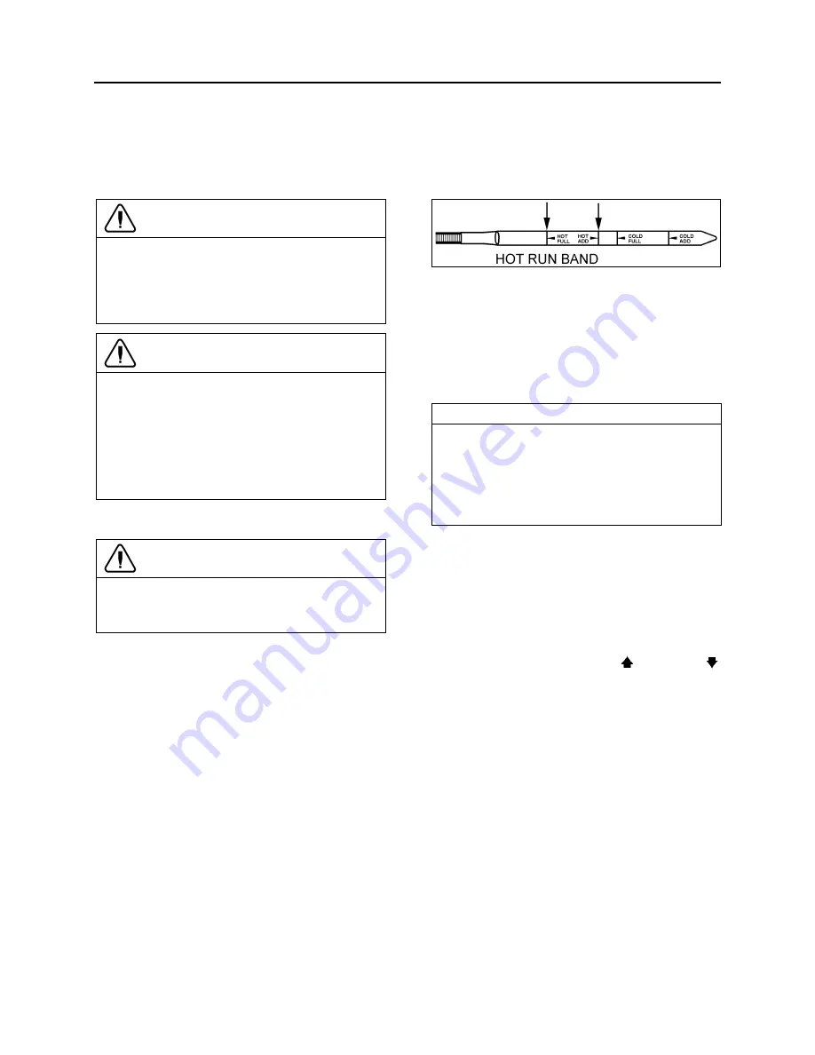
level. The safe operating level is anywhere
within the HOT RUN band on the dipstick.
Repeat the check procedure to verify the
reading.
5. If the level
is not
within this band, add or drain
fluid as necessary to bring the level within the
HOT RUN band. (Fig. 5).
FIGURE 5: HOT CHECK
07049
6. Be sure fluid level checks are consistent.
Check level more than once and if readings
are not consistent, check to be sure the
transmission breather is clean and not
clogged. If readings are still not consistent,
contact your nearest Allison dealer or
distributor.
NOTE
The Cold Check is more appropriate for
verifying the oil level after the first fill-up. In case
of conflict, the Hot Check has priority over the
Cold Check;
the fluid level check using the
pushbutton shift selector has priority over
the Hot Check.
3.2 FLUID LEVEL CHECK USING THE
PUSHBUTTON SHIFT SELECTOR
Oil level codes are obtained as follows:
1. Park vehicle on a level surface, select «N»
(neutral) on the pushbutton shift selector
and apply parking brake.
2. Press simultaneously the (Up) and
(Down) arrow buttons once.
3. Oil level codes are displayed in 2 minutes
(e.g. display will flash and 8, 7, 6, 5, ...;
countdown will occur during the 2 minutes)
once the following parameters are met:
o
Waiting time, vehicle must be stationary
for at least 2 minutes to allow the oil to
settle;
o
Engine at idle;
o
Oil at normal operating temperature,
between 140°F (60°C) and 220°F (104°C);
o
Transmission in «N» (Neutral);
o
Transmission output shaft stopped;
o
Oil level sensor present and working.
Summary of Contents for X3-45 2016
Page 4: ......
Page 16: ...Section 00 GENERAL INFORMATION PA1593 12 FIGURE 12 METRIC US STANDARD CONVERSION TABLE 00005...
Page 17: ...Section 00 GENERAL INFORMATION 13 PA1593 FIGURE 13 CONVERSION CHART 00006...
Page 18: ......
Page 26: ......
Page 58: ......
Page 72: ...Section 04 EXHAUST AND AFTERTREATMENT SYSTEM PA1593 14 7 TORQUE SPECIFICATIONS...
Page 73: ...SECTION 04 EXHAUST AND AFTERTREATMENT SYSTEM PA1593 15...
Page 74: ...Section 04 EXHAUST AND AFTERTREATMENT SYSTEM PA1593 16...
Page 76: ......
Page 96: ......
Page 134: ......
Page 176: ...SECTION 06B ELECTRICAL 38 overcurrent working Circuit 306 shorted to ground...
Page 180: ......
Page 202: ......
Page 205: ...Section 09 PROPELLER SHAFT PA1593 3 FIGURE 1 PROPELLER SHAFT ASSEMBLY 09002...
Page 256: ......
Page 268: ......
Page 295: ...SECTION 16 SUSPENSION PA1593 9 2 5 TORQUE SPECIFICATIONS...
Page 296: ...Section 16 SUSPENSION PA1593 10...
Page 297: ...Section 16 SUSPENSION PA1593 11...
Page 314: ......
Page 380: ......
Page 388: ......
Page 413: ...Section 22 HEATING AND AIR CONDITIONING PA1593 15 FIGURE 18 REFRIGERANT CIRCUIT CENTRAL SYSTEM...
Page 433: ...Section 22 HEATING AND AIR CONDITIONING PA1593 35 FIGURE 36 CENTRAL HEATING SYSTEM COMPONENTS...


