Section 07: TRANSMISSION
PA1593
11
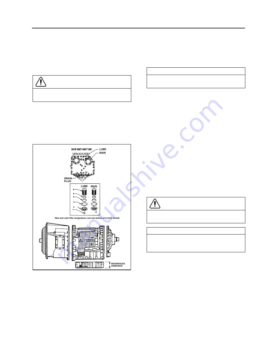
4. To install filters, pre-lube and install the two O-
rings, the two square cut seals followed by the
filters (lube the O-ring in filter cartridge only)
into the filter compartment. Index each
filter/cover assembly to holes in channel
plate/sump. Push the cover assembly in by
hand to seat the seals.
CAUTION
Do not use bolts to draw the cover to sump.
This can damage the cover, seal, or sump.
5. Install twelve bolts and both covers, and then
tighten to 38-45 lbf-ft (51-61 Nm).
6. Inspect the drain plug and O-ring. Replace if
necessary. Reinstall the drain plug and tighten
to 18-24 lbf-ft (25-32 Nm).
7. Reinstall transmission protective panel
FIGURE 6: DRAIN PLUG AND FILTERS
07074
Fluid loss with filter change only
When changing main and lube filters at
recommended intervals, approximate fluid loss
for each filter as follows:
Main filter = 2 quarts (1.9 liters)
Lube filter =8 quarts (7.6 liters)
Refilling Transmission
The amount of refill fluid is less than the amount
used for the initial fill. Fluid remains in the
external circuits and transmission cavities after
draining the transmission.
NOTE
Quantities listed above are approximations and
do not include external oil cooler lines.
Using the oil level dipstick filler tube, refill with
24 US qts (23 liters) [28 US qts (26.5 liters) if
equipped with retarder] and check the oil level
using the
Fluid Level Check Using
Pushbutton Shift Selector
procedure in this
section.
4. ALLISON TRANSMISSION REMOVAL
The following procedure deals with the removal of
the Allison transmission without removing the
power plant cradle from vehicle. The methods
used to support the transmission and engine
depend upon conditions and available equipment.
1. Select transmission's "NEUTRAL" position,
apply parking brake, then set battery master
switch to the "OFF" position.
2. Jack up vehicle, then place safety supports
underneath body.
CAUTION
Only the recommended jacking points must be
used as outlined in Section 18, "BODY".
NOTE
For more clearance between the tag axle and
transmission, the tag axle may be unloaded
and jacked up or retracted (if applicable).
3. Remove engine splash guards and protective
panels surrounding transmission.
4.
Remove cross member from under
transmission.
5. Remove the transmission drain plug and allow
oil to drain. Inspect the drain plug washer and
replace it if necessary. Reinstall the drain plug
and tighten to 33-41 lbf-ft (45-56 Nm) (see
"3.10 OIL AND FILTER CHANGE"
in this
section.
Summary of Contents for X3-45 2016
Page 4: ......
Page 16: ...Section 00 GENERAL INFORMATION PA1593 12 FIGURE 12 METRIC US STANDARD CONVERSION TABLE 00005...
Page 17: ...Section 00 GENERAL INFORMATION 13 PA1593 FIGURE 13 CONVERSION CHART 00006...
Page 18: ......
Page 26: ......
Page 58: ......
Page 72: ...Section 04 EXHAUST AND AFTERTREATMENT SYSTEM PA1593 14 7 TORQUE SPECIFICATIONS...
Page 73: ...SECTION 04 EXHAUST AND AFTERTREATMENT SYSTEM PA1593 15...
Page 74: ...Section 04 EXHAUST AND AFTERTREATMENT SYSTEM PA1593 16...
Page 76: ......
Page 96: ......
Page 134: ......
Page 176: ...SECTION 06B ELECTRICAL 38 overcurrent working Circuit 306 shorted to ground...
Page 180: ......
Page 202: ......
Page 205: ...Section 09 PROPELLER SHAFT PA1593 3 FIGURE 1 PROPELLER SHAFT ASSEMBLY 09002...
Page 256: ......
Page 268: ......
Page 295: ...SECTION 16 SUSPENSION PA1593 9 2 5 TORQUE SPECIFICATIONS...
Page 296: ...Section 16 SUSPENSION PA1593 10...
Page 297: ...Section 16 SUSPENSION PA1593 11...
Page 314: ......
Page 380: ......
Page 388: ......
Page 413: ...Section 22 HEATING AND AIR CONDITIONING PA1593 15 FIGURE 18 REFRIGERANT CIRCUIT CENTRAL SYSTEM...
Page 433: ...Section 22 HEATING AND AIR CONDITIONING PA1593 35 FIGURE 36 CENTRAL HEATING SYSTEM COMPONENTS...


