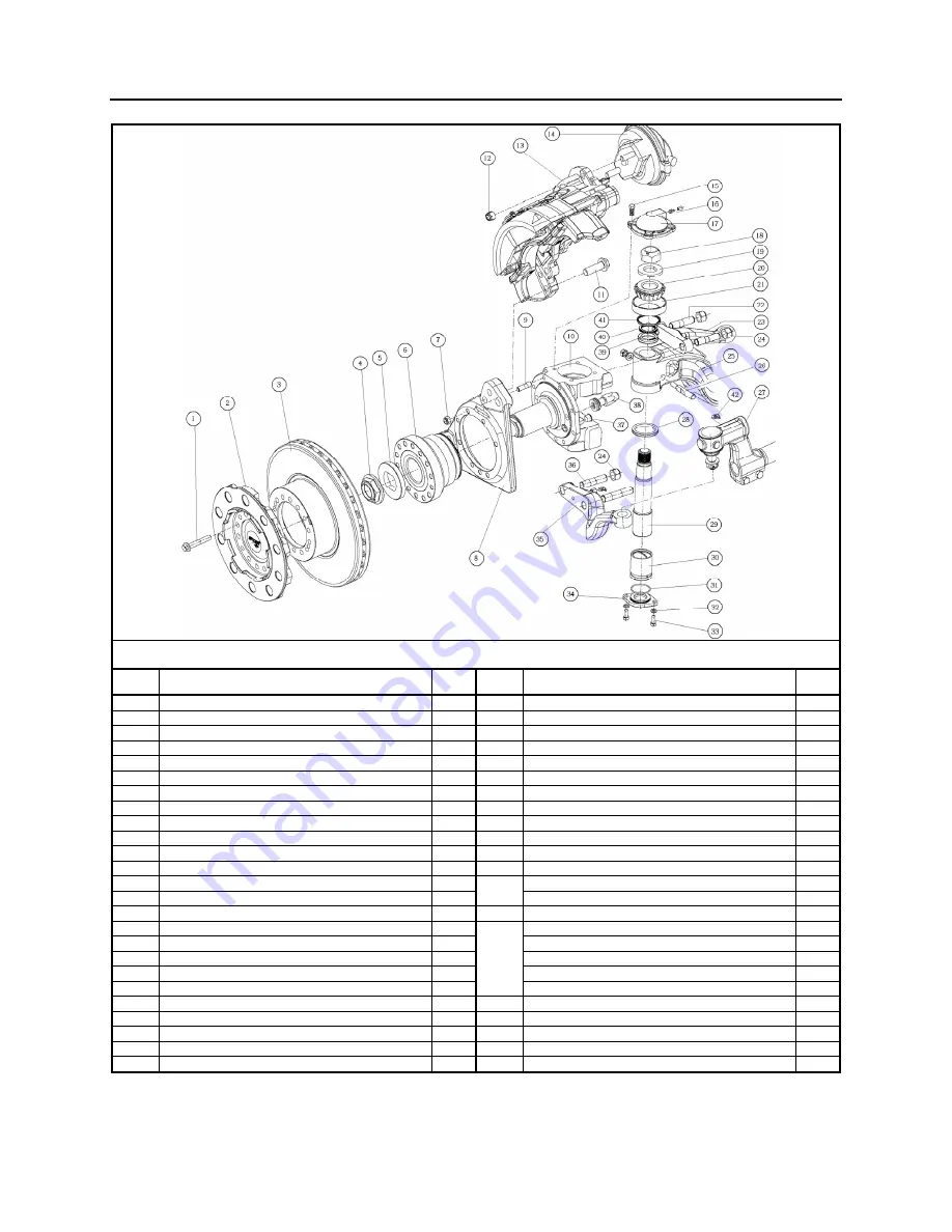
Section 10: FRONT AXLE
PA1593
3
TYPICAL S84U AXLE
ITEM DESCRIPTION
QTY ITEM DESCRIPTION
QTY
1
Flanged Bolt 161-197 lbf-ft
28
26
Draw key, Nut, Washer 51-62 lbf-ft
2
2
Hub
2
27
Tie Rod End
2
3
Brake Disc
2
28
V-Ring Seal
2
4
Stake Hub Nut 563-687 lbf-ft
2
29
Kingpin
2
5
Collet Washer
2
30
Kingpin - Bushing
2
6
Hub Bearing
2
31
O-Ring Seal
2
7
Nut – Self Lock 85-103 lbf-ft
16
32
Washer
4
8
Brake Mounting Bracket
2
33
Screw 26-32 lbf-ft
4
9
Stud
16
34
Cap - Knuckle Bottom
2
10
Knuckle
2
35
Bottom Steering Lever
2
11
Brake Fixing – Bolt 325-375 lbf-ft
12
36
Bottom Steering Lever - Stud
4
12
Nut – Self Lock 133-155 lbf-ft
4
37
Abs Sensor - Bush
2
13
Brake
1
38
Back Lock - Stop Bolt 85-103 lbf-ft
2
14
Brake Chamber
2
Front Lock - Stop Bolt 85-103 lbf-ft
1
15
Screw 51-62 lbf-ft
8
39
Sleeve - Knuckle Bearing
2
16
Grease Fitting
4
40
Shim .005"
8
17
Cap - Knuckle Top
2
Shim .010"
8
18
Nut – Self Lock 500-700 lbf-ft
2
Shim .015"
8
19 Washer
2
Shim
.008"
4
20
Bearing Cone
2
Shim .006"
2
21
Bearing Cup
2
41
Oil Seal
2
22
Steering Lever - Stud
4
42
Grease Fitting
2
23 Steering
Lever
2
24
Nut - Self Lock
4
25 Axle,
I-Beam
1
Additional torque specifications applicable to the front axle are grouped with information regarding the front suspension. Please refer
to Section 16: SUSPENSION of this manual.
Summary of Contents for X3-45 2016
Page 4: ......
Page 16: ...Section 00 GENERAL INFORMATION PA1593 12 FIGURE 12 METRIC US STANDARD CONVERSION TABLE 00005...
Page 17: ...Section 00 GENERAL INFORMATION 13 PA1593 FIGURE 13 CONVERSION CHART 00006...
Page 18: ......
Page 26: ......
Page 58: ......
Page 72: ...Section 04 EXHAUST AND AFTERTREATMENT SYSTEM PA1593 14 7 TORQUE SPECIFICATIONS...
Page 73: ...SECTION 04 EXHAUST AND AFTERTREATMENT SYSTEM PA1593 15...
Page 74: ...Section 04 EXHAUST AND AFTERTREATMENT SYSTEM PA1593 16...
Page 76: ......
Page 96: ......
Page 134: ......
Page 176: ...SECTION 06B ELECTRICAL 38 overcurrent working Circuit 306 shorted to ground...
Page 180: ......
Page 202: ......
Page 205: ...Section 09 PROPELLER SHAFT PA1593 3 FIGURE 1 PROPELLER SHAFT ASSEMBLY 09002...
Page 256: ......
Page 268: ......
Page 295: ...SECTION 16 SUSPENSION PA1593 9 2 5 TORQUE SPECIFICATIONS...
Page 296: ...Section 16 SUSPENSION PA1593 10...
Page 297: ...Section 16 SUSPENSION PA1593 11...
Page 314: ......
Page 380: ......
Page 388: ......
Page 413: ...Section 22 HEATING AND AIR CONDITIONING PA1593 15 FIGURE 18 REFRIGERANT CIRCUIT CENTRAL SYSTEM...
Page 433: ...Section 22 HEATING AND AIR CONDITIONING PA1593 35 FIGURE 36 CENTRAL HEATING SYSTEM COMPONENTS...


