Section 10: FRONT AXLE
PA1593
9
and a tendency for the wheels to return to the
straight-ahead position after taking a turn.
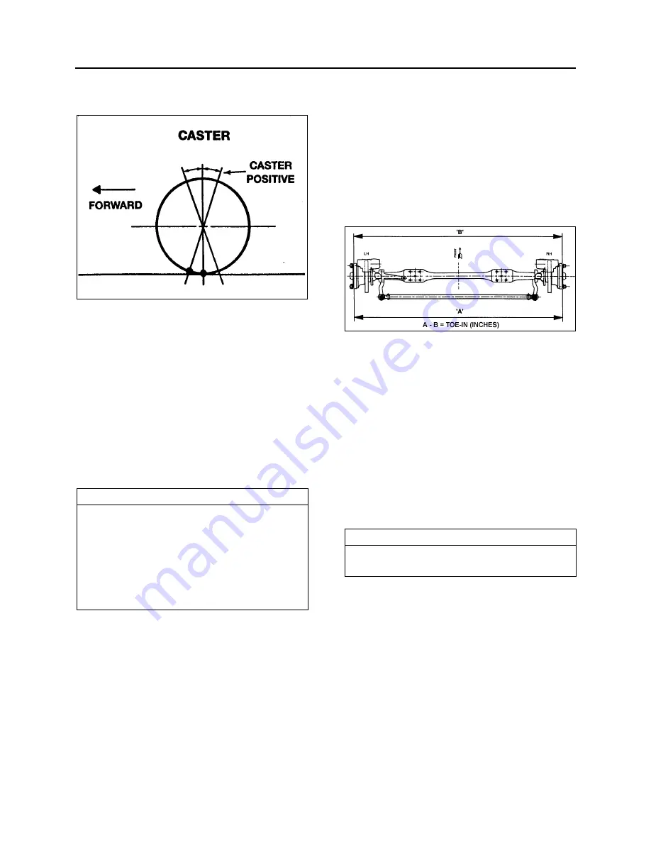
FIGURE 4: CASTER
10007
Excessive caster results in hard steering around
corners. A shimmy may also develop when
returning to the straight ahead position (pulling
out of curves).
Insufficient caster will cause wandering and
steering instability. Caster variations may be
caused by a bent axle, tilting or distortion of the
side suspension supports, damaged radius rod
bushings, or unequal tightening of the front and
rear suspension support bolts. Incorrect caster
must be corrected by replacing the damaged
suspension parts. A precision instrument should
be used to measure the caster.
NOTE
The caster of this vehicle is factory set and is
not adjustable. However, if after replacing
damaged parts or in case of improper caster
due to irregular setting, the front axle caster
needs adjustment; it can be adjusted by means
of shims (Prevost #110663) on the left-hand
side upper radius rod support in order to obtain
minor adjustment.
6.8
FRONT WHEEL TOE-IN
Wheel toe-in is the degree (usually expressed in
fractions of an inch) to which the forward part of
the vehicle front wheels are closer together than
the rear part, measured at wheel centerline height
with the wheels in the normal ‘’straight-ahead’’
position of the steering gear.
Incorrect toe-in results in excessive tire wear
caused by side slippage and also steering
instability with a tendency to wander. Toe-in may
be measured from the center of tire tread or from
the inside of the tires. Take measurements at
both front and rear of axle (see ’’A and ‘’B’’ in fig.
5).
When setting toe-in adjustment, the front
suspension must be neutralized; that is, all
component parts must be in the same relative
position when marking the adjustment as they
will be when in operation.
To neutralize the suspension, the vehicle must
be rolled forward, approximately ten feet.
FIGURE 5: TOE-IN MEASUREMENTS
10032
For toe-in specifications, refer to paragraph 8
‘’Specifications’’ in this section.
By rolling the vehicle forward, all tolerances in
the front suspension are taken up and the
suspension is then in its normal operating
position. Neutralizing the front suspension is
extremely important, especially if the vehicle has
been jacked up in order to mark the tires.
Otherwise, the front wheels will not return to
their normal operating position due to the tires
gripping the floor surface when the vehicle jack
is lowered.
NOTE
‘’Toe-in’’ measurements must be taken at the
horizontal axis of the wheel centerline.
Summary of Contents for X3-45 2016
Page 4: ......
Page 16: ...Section 00 GENERAL INFORMATION PA1593 12 FIGURE 12 METRIC US STANDARD CONVERSION TABLE 00005...
Page 17: ...Section 00 GENERAL INFORMATION 13 PA1593 FIGURE 13 CONVERSION CHART 00006...
Page 18: ......
Page 26: ......
Page 58: ......
Page 72: ...Section 04 EXHAUST AND AFTERTREATMENT SYSTEM PA1593 14 7 TORQUE SPECIFICATIONS...
Page 73: ...SECTION 04 EXHAUST AND AFTERTREATMENT SYSTEM PA1593 15...
Page 74: ...Section 04 EXHAUST AND AFTERTREATMENT SYSTEM PA1593 16...
Page 76: ......
Page 96: ......
Page 134: ......
Page 176: ...SECTION 06B ELECTRICAL 38 overcurrent working Circuit 306 shorted to ground...
Page 180: ......
Page 202: ......
Page 205: ...Section 09 PROPELLER SHAFT PA1593 3 FIGURE 1 PROPELLER SHAFT ASSEMBLY 09002...
Page 256: ......
Page 268: ......
Page 295: ...SECTION 16 SUSPENSION PA1593 9 2 5 TORQUE SPECIFICATIONS...
Page 296: ...Section 16 SUSPENSION PA1593 10...
Page 297: ...Section 16 SUSPENSION PA1593 11...
Page 314: ......
Page 380: ......
Page 388: ......
Page 413: ...Section 22 HEATING AND AIR CONDITIONING PA1593 15 FIGURE 18 REFRIGERANT CIRCUIT CENTRAL SYSTEM...
Page 433: ...Section 22 HEATING AND AIR CONDITIONING PA1593 35 FIGURE 36 CENTRAL HEATING SYSTEM COMPONENTS...


