Section 11: REAR AXLES
PA1593
3
Maintenance of the axle mountings consists
primarily in a regular and systematic inspection of
the air suspension units and radius rods, as
directed in Section 16,
"Suspension".
1.3.1
Checking and Adjusting the Oil Level
DANGER
Before servicing, park safely over a repair pit;
apply parking brake, stop engine and set
battery master switch to the "OFF" position.
1. Make sure the vehicle is parked on a level
surface.
WARNING
Check the oil level when the axle is at room
temperature. When hot, the oil temperature
may be 190ºF (88ºC) or more and can cause
burns. Also, a correct reading is not obtained
when the axle is warm or hot.
2. Make sure the axle is "cold" or at room
temperature.
3. Clean the area around the fill plug. Remove
the fill plug from the differential axle housing
bowl (Fig. 4).
4. The oil level must be even with the bottom of
the hole of the fill plug.
a. If oil flows from the hole when the plug is
loosened, the oil level is high. Drain the
oil to the correct level.
b. If the oil level is below the bottom of the
hole of the fill plug, add the specified oil.
5. Install and tighten the fill plug to 35-50 lbf-ft
(48-67 Nm).
1.3.2
Draining and Replacing the Oil
DANGER
Before servicing, park safely over a repair pit,
apply parking brake, stop engine and set
battery master switch to the "OFF" position.
1. Make sure the vehicle is parked on a level
surface. Put a large container under the
axle's drain plug.
NOTE
Drain the oil when the axle is warm.
2. Remove the drain plug from the bottom of the
axle. Drain and discard the oil in an
environment friendly manner.
3. Install and tighten the drain plug to 35-50
lbf-ft (48-67 Nm).
4. Clean the area around the fill plug. Remove
the fill plug from the differential housing bowl.
5. Add the specified oil until the oil level is even
with the bottom of the hole of the fill plug.
Allow the oil to flow through the axle and
check the oil level again (lube capacity 41
pints [13,3 liters]).
CAUTION
The differential overheats when the oil
temperature rises above 250ºF (120ºC).
6. Install and tighten the fill plug to 35-50 lbf-ft
(48-67 Nm).
1.3.3
Speed Sensors (Anti-Lock Brake
system, ABS)
For removing and installing the drive axle speed
sensors (for anti-lock brake systems, ABS), refer
to Section 12:
‘’Brake and Air System’’
and to
Rockwell WABCO Maintenance Manual:
“Anti-
Lock Brake Systems For Trucks, Tractors and
Buses"
, annexed at the end of section 12.
1.4
REMOVAL AND REINSTALLATION
The following procedure deals with the removal
of the drive axle assembly and its attachments
as a unit. The method used to support the axle
during removal and disassembly depends upon
local conditions and available equipment.
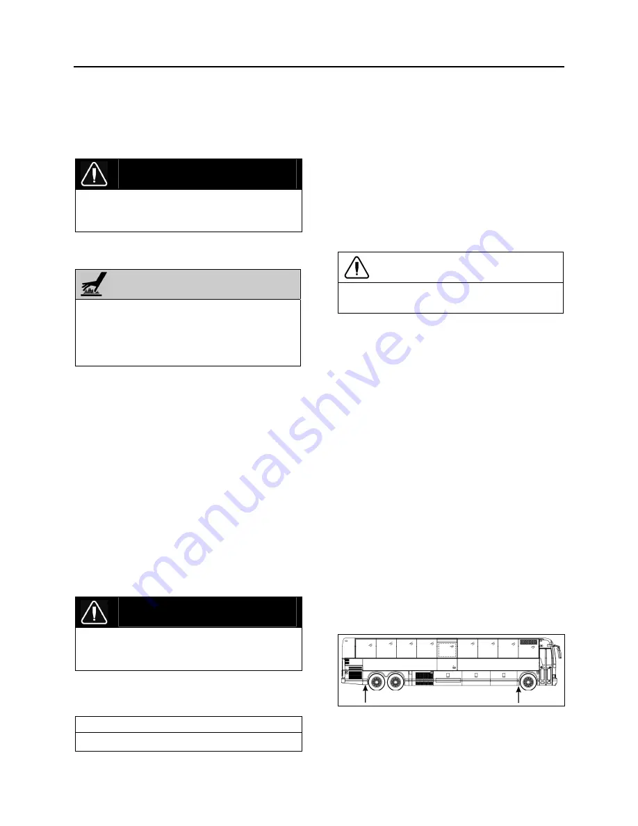
1. Raise vehicle by its jacking points on the
body (fig. 4 or see Section 18,
"Body"
under
heading
"Vehicle Jacking Points").
Place jack
stands under frame. Remove drive axle
wheels (if required, refer to Section 13,
"Wheels, Hubs And Tires".
FIGURE 4: JACKING POINTS ON FRAME (TYPICAL)
18618
Summary of Contents for X3-45 2016
Page 4: ......
Page 16: ...Section 00 GENERAL INFORMATION PA1593 12 FIGURE 12 METRIC US STANDARD CONVERSION TABLE 00005...
Page 17: ...Section 00 GENERAL INFORMATION 13 PA1593 FIGURE 13 CONVERSION CHART 00006...
Page 18: ......
Page 26: ......
Page 58: ......
Page 72: ...Section 04 EXHAUST AND AFTERTREATMENT SYSTEM PA1593 14 7 TORQUE SPECIFICATIONS...
Page 73: ...SECTION 04 EXHAUST AND AFTERTREATMENT SYSTEM PA1593 15...
Page 74: ...Section 04 EXHAUST AND AFTERTREATMENT SYSTEM PA1593 16...
Page 76: ......
Page 96: ......
Page 134: ......
Page 176: ...SECTION 06B ELECTRICAL 38 overcurrent working Circuit 306 shorted to ground...
Page 180: ......
Page 202: ......
Page 205: ...Section 09 PROPELLER SHAFT PA1593 3 FIGURE 1 PROPELLER SHAFT ASSEMBLY 09002...
Page 256: ......
Page 268: ......
Page 295: ...SECTION 16 SUSPENSION PA1593 9 2 5 TORQUE SPECIFICATIONS...
Page 296: ...Section 16 SUSPENSION PA1593 10...
Page 297: ...Section 16 SUSPENSION PA1593 11...
Page 314: ......
Page 380: ......
Page 388: ......
Page 413: ...Section 22 HEATING AND AIR CONDITIONING PA1593 15 FIGURE 18 REFRIGERANT CIRCUIT CENTRAL SYSTEM...
Page 433: ...Section 22 HEATING AND AIR CONDITIONING PA1593 35 FIGURE 36 CENTRAL HEATING SYSTEM COMPONENTS...


