Section 12: BRAKE AND AIR SYSTEM
Section 12 Updated Sept. 2015
X3-45 Commuter PA1593 DOB 2400-2489
5
The accessory air tank is installed close to the
front axle and is provided with a bottom drain
valve (Fig. 1).
Purge the reservoir by its drain valve every
12,500 miles (20 000 km) or once a year,
whichever comes first.
FIGURE 2: REAR VALVE LOCATION (TYPICAL)
12211
3.1.4 Secondary Air Tank
This tank is located in the front wheelhousing,
behind the steering axle (Fig. 1). It is provided
with a bottom drain valve.
Purge this reservoir every 12,500 miles (20 000
km) or once a year, whichever comes first.
3.1.5 Kneeling Air Tank
The kneeling air tank is located in the front
wheelhousing (Fig. 1), and is provided with a
bottom drain valve.
3.1.6 Parking Brakes Overrule Air Tank
The parking brakes overrule air tank is installed
at the ceiling of the rear baggage compartment,
on the L.H. side, and is provided with a bottom
drain valve.
3.2
PING TANK
The ping tank is located in the engine compart-
ment; it is accessible through the engine
compartment R.H. side door. It is used to
dissipate heat and to reduce noise produced by
the air compressor cycling on and off.
4. AIR SYSTEM EMERGENCY FILL VALVES
All vehicles come equipped with two emergency
fill valves that enable system pressurization by
an external source such as an air compressor.
The rear valve is located in the engine
compartment and is accessible from engine R.H.
side door (Fig 2). It is positioned close to the
door opening.
CAUTION
Maximum allowable air pressure is 125 psi
(860 kPa). Air filled through these two points
will pass through the standard air filtering
system provided by Prevost. Do not fill system
by any point on the system.
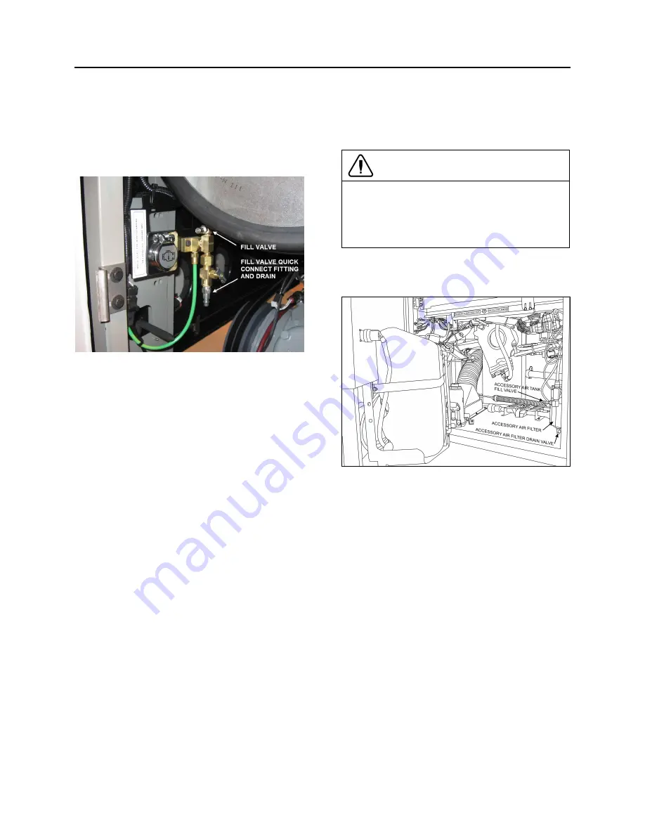
The front valve is located in the front service
compartment close to R.H. side of door frame
(Fig. 3).
FIGURE 3: FRONT SERVICE COMPARTMENT
12210
These two air system emergency fill valves are
fitted with the same valve stems as standard
tires, and can be filled by any standard external
air supply line.
The rear air system emergency fill valve will
supply air for all systems (brakes, suspension
and accessories) while the front fill valve will
supply air for accessories only.
Summary of Contents for X3-45 2016
Page 4: ......
Page 16: ...Section 00 GENERAL INFORMATION PA1593 12 FIGURE 12 METRIC US STANDARD CONVERSION TABLE 00005...
Page 17: ...Section 00 GENERAL INFORMATION 13 PA1593 FIGURE 13 CONVERSION CHART 00006...
Page 18: ......
Page 26: ......
Page 58: ......
Page 72: ...Section 04 EXHAUST AND AFTERTREATMENT SYSTEM PA1593 14 7 TORQUE SPECIFICATIONS...
Page 73: ...SECTION 04 EXHAUST AND AFTERTREATMENT SYSTEM PA1593 15...
Page 74: ...Section 04 EXHAUST AND AFTERTREATMENT SYSTEM PA1593 16...
Page 76: ......
Page 96: ......
Page 134: ......
Page 176: ...SECTION 06B ELECTRICAL 38 overcurrent working Circuit 306 shorted to ground...
Page 180: ......
Page 202: ......
Page 205: ...Section 09 PROPELLER SHAFT PA1593 3 FIGURE 1 PROPELLER SHAFT ASSEMBLY 09002...
Page 256: ......
Page 268: ......
Page 295: ...SECTION 16 SUSPENSION PA1593 9 2 5 TORQUE SPECIFICATIONS...
Page 296: ...Section 16 SUSPENSION PA1593 10...
Page 297: ...Section 16 SUSPENSION PA1593 11...
Page 314: ......
Page 380: ......
Page 388: ......
Page 413: ...Section 22 HEATING AND AIR CONDITIONING PA1593 15 FIGURE 18 REFRIGERANT CIRCUIT CENTRAL SYSTEM...
Page 433: ...Section 22 HEATING AND AIR CONDITIONING PA1593 35 FIGURE 36 CENTRAL HEATING SYSTEM COMPONENTS...


