Section 12: BRAKE AND AIR SYSTEM
6
X3-45 Commuter PA1593 DOB 2400-2489
Section 12 Updated Sept. 2015
5. ACCESSORY AIR FILTER
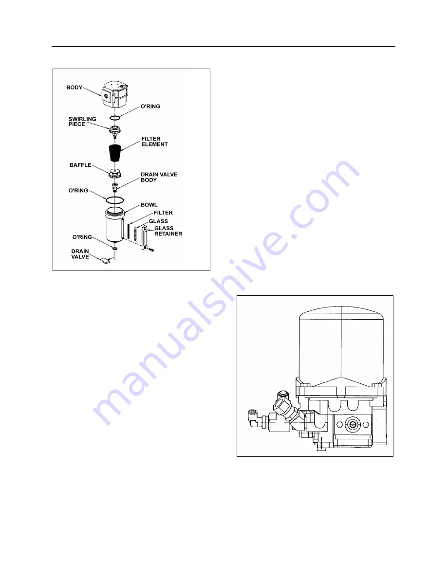
FIGURE 4: ACCESSORY AIR FILTER
12088
This filter is located inside the front service
compartment (Fig. 3). Its main function consists
in filtering the air supplied to the accessory air
system, when connected to an external supply
line. Ensure filter is purged whenever supplying
the system with an external air line and at least
every 12,500 miles (20 000 km). To purge, open
drain valve (Fig. 4), let the moisture come out,
then close the drain valve.
5.1
FILTER ELEMENT REPLACEMENT
Replace filter element whichever of the following
occurs first: every 100,000 miles (160 000 km),
every two years, or whenever differential
pressure exceeds 15 psi (105 kPa) between filter
inlet and outlet ports. Check condition of all three
O-rings for damage. Replace when necessary
(Fig. 4).
5.2
CLEANING
Clean filter body and bowl with a warm water and
soap solution. Rinse thoroughly with clean water.
Blow dry with compressed air making sure the
air stream is moisture free and clean. Pay
particular attention to the internal passages.
Inspect all parts for damage and replace if
necessary.
6. AIR GAUGES (PRIMARY, SECONDARY
AND ACCESSORY)
The air pressure gauges, located on the
dashboard (see
"Operator's Manual"
), are
connected to the DC-4 double check valve,
located on the pneumatic accessory panel in the
front service compartment.
The latter is connected to the air lines running
from the primary and secondary air tanks, as
shown on the pneumatic system diagram
provided in the technical publications box. The
accessory air gauge is connected to the
accessory air tank using the drain valve
connector. The vehicle should never be set in
motion until the buzzer alarm and warning lights
turn off, i.e. when air pressure registers at least
66 psi (455 kPa). Moreover, if pressure drops
below 66 psi (455 kPa), the
"Low air pressure"
warning lights will turn on, and the
"Low air
pressure"
buzzer will sound. Stop the vehicle
immediately, determine and correct the cause(s)
of pressure loss. Check the gauges regularly
with an accurate test gauge. Replace the gauge
with a new unit if there is a difference of 4 psi (27
kPa) or more in the reading.
7. AIR FILTER/DRYER
FIGURE 5: HALDEX AIR FILTER DRYER
12194
The air filter/dryer is located in front of rear
wheelhousing (Fig. 1 & 5). Its purpose is to
remove moisture that could damage the air
system before the air enters the system
reservoir. The air filter/dryer also filters the air to
remove dirt, compressor oil, and other
contaminants that can damage the system.
Summary of Contents for X3-45 2016
Page 4: ......
Page 16: ...Section 00 GENERAL INFORMATION PA1593 12 FIGURE 12 METRIC US STANDARD CONVERSION TABLE 00005...
Page 17: ...Section 00 GENERAL INFORMATION 13 PA1593 FIGURE 13 CONVERSION CHART 00006...
Page 18: ......
Page 26: ......
Page 58: ......
Page 72: ...Section 04 EXHAUST AND AFTERTREATMENT SYSTEM PA1593 14 7 TORQUE SPECIFICATIONS...
Page 73: ...SECTION 04 EXHAUST AND AFTERTREATMENT SYSTEM PA1593 15...
Page 74: ...Section 04 EXHAUST AND AFTERTREATMENT SYSTEM PA1593 16...
Page 76: ......
Page 96: ......
Page 134: ......
Page 176: ...SECTION 06B ELECTRICAL 38 overcurrent working Circuit 306 shorted to ground...
Page 180: ......
Page 202: ......
Page 205: ...Section 09 PROPELLER SHAFT PA1593 3 FIGURE 1 PROPELLER SHAFT ASSEMBLY 09002...
Page 256: ......
Page 268: ......
Page 295: ...SECTION 16 SUSPENSION PA1593 9 2 5 TORQUE SPECIFICATIONS...
Page 296: ...Section 16 SUSPENSION PA1593 10...
Page 297: ...Section 16 SUSPENSION PA1593 11...
Page 314: ......
Page 380: ......
Page 388: ......
Page 413: ...Section 22 HEATING AND AIR CONDITIONING PA1593 15 FIGURE 18 REFRIGERANT CIRCUIT CENTRAL SYSTEM...
Page 433: ...Section 22 HEATING AND AIR CONDITIONING PA1593 35 FIGURE 36 CENTRAL HEATING SYSTEM COMPONENTS...


