Section 12: BRAKE AND AIR SYSTEM
Section 12 Updated Sept. 2015
X3-45 Commuter PA1593 DOB 2400-2489
13
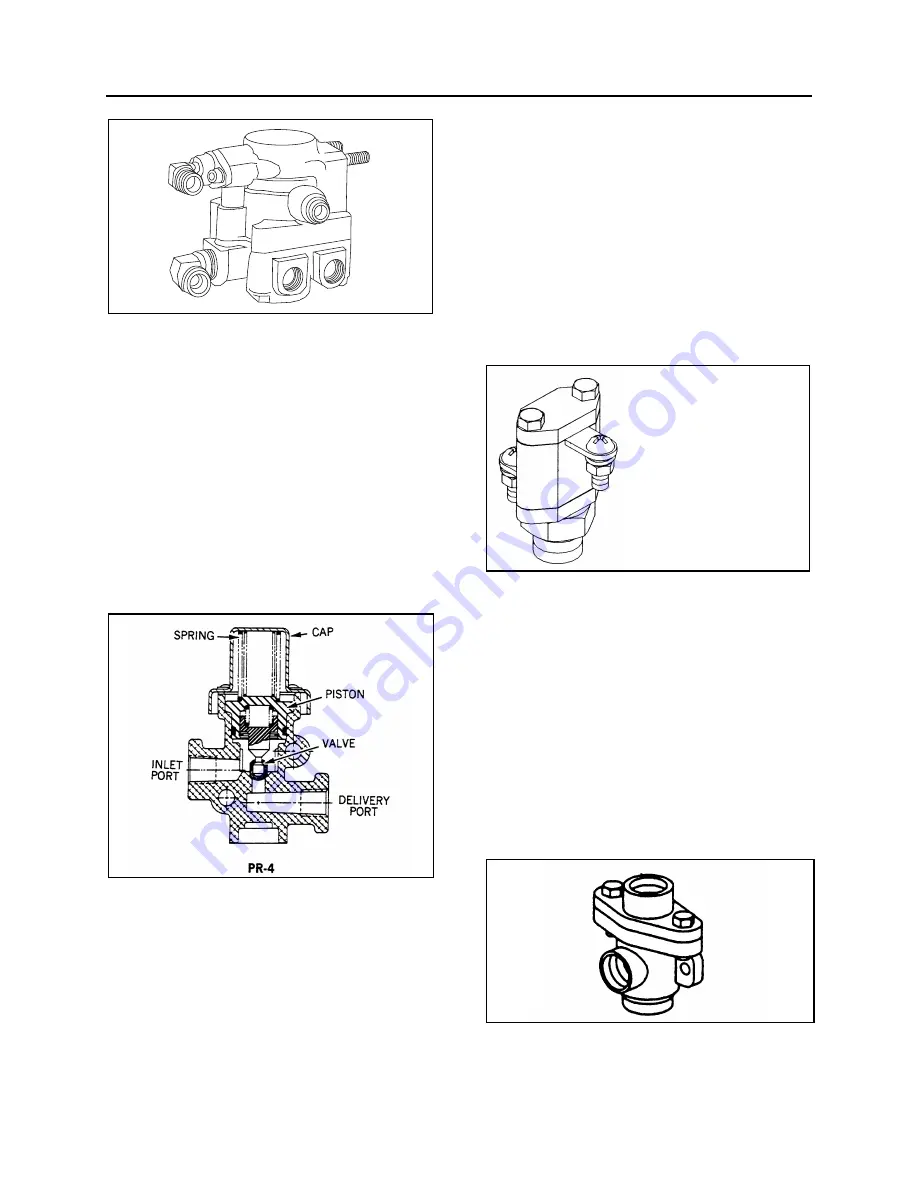
FIGURE 19: SR-7
12206
21. PRESSURE PROTECTION VALVE (PR-4)
Maintenance and repair information on the
pressure protection valve is supplied in the
applicable booklet annexed to this section under
reference number SD-03-2010.
The air system includes two pressure protection
valves (Fig. 20). One valve is installed on the
manifold block, and insures at all times a
minimum pressure of 70 psi (482 kPa) in the
suspension air system in the event that a
pressure drop occurs in either the suspension air
system or accessory air system. This valve is
located in the front service compartment beside
the air filter.
FIGURE 20: PR-4
12174
The other valve is installed on the accessory air
tank, and insures a minimum pressure of 70 psi
(482 kPa) in the accessory air system in the
event that a pressure drop occurs in either the
suspension air system or braking air system
(refer to Fig. 1 for accessory air tank location).
22. LOW PRESSURE INDICATOR (LP-3)
Maintenance and repair information on the low
pressure indicators is supplied in the applicable
booklet annexed to this section under reference
number SD-06-1600.
The air system includes two low pressure
switches (Fig. 21), both located on the
pneumatic accessory panel in the front service
compartment. One serves for the parking brake
signal, its pressure setting is 66 ± 6 psi (455 ± 40
kPa). The remaining pressure switch monitors
the parking brake telltale panel indicator; its
pressure setting is 30 psi (205 kPa).
FIGURE 21: LP-3
12214
23. SHUTTLE-TYPE DOUBLE CHECK VALVE
(DC-4)
Maintenance and repair information on the
shuttle-type double check valve is supplied in the
applicable booklet annexed to this section under
reference number SD-03-2202.
The double check valve is located on the
pneumatic accessory panel in the front service
compartment. In the event of a pressure drop in
either the primary or secondary system, this unit
will protect the emergency /parking brake control
valve and the intact portion of the air system
from pressure loss.
FIGURE 22: DC-4
12134
Summary of Contents for X3-45 2016
Page 4: ......
Page 16: ...Section 00 GENERAL INFORMATION PA1593 12 FIGURE 12 METRIC US STANDARD CONVERSION TABLE 00005...
Page 17: ...Section 00 GENERAL INFORMATION 13 PA1593 FIGURE 13 CONVERSION CHART 00006...
Page 18: ......
Page 26: ......
Page 58: ......
Page 72: ...Section 04 EXHAUST AND AFTERTREATMENT SYSTEM PA1593 14 7 TORQUE SPECIFICATIONS...
Page 73: ...SECTION 04 EXHAUST AND AFTERTREATMENT SYSTEM PA1593 15...
Page 74: ...Section 04 EXHAUST AND AFTERTREATMENT SYSTEM PA1593 16...
Page 76: ......
Page 96: ......
Page 134: ......
Page 176: ...SECTION 06B ELECTRICAL 38 overcurrent working Circuit 306 shorted to ground...
Page 180: ......
Page 202: ......
Page 205: ...Section 09 PROPELLER SHAFT PA1593 3 FIGURE 1 PROPELLER SHAFT ASSEMBLY 09002...
Page 256: ......
Page 268: ......
Page 295: ...SECTION 16 SUSPENSION PA1593 9 2 5 TORQUE SPECIFICATIONS...
Page 296: ...Section 16 SUSPENSION PA1593 10...
Page 297: ...Section 16 SUSPENSION PA1593 11...
Page 314: ......
Page 380: ......
Page 388: ......
Page 413: ...Section 22 HEATING AND AIR CONDITIONING PA1593 15 FIGURE 18 REFRIGERANT CIRCUIT CENTRAL SYSTEM...
Page 433: ...Section 22 HEATING AND AIR CONDITIONING PA1593 35 FIGURE 36 CENTRAL HEATING SYSTEM COMPONENTS...


