Section 13: WHEELS, HUBS & TIRES
PA1593
6
6.1 CARE OF WHEELS
Check for cracks in wheels, especially around
the fixing holes, studs, nuts and washers. If in
doubt, renew.
Do not simply retighten very loose wheel fixings
or wheels that are continually becoming loose.
Find out why they are loose and whether any
damage has been caused.
Use trained personnel and keep records of all
attention to wheels and fixings, including which
parts were renewed and when.
7. FRONT AND TAG AXLE WHEEL HUBS
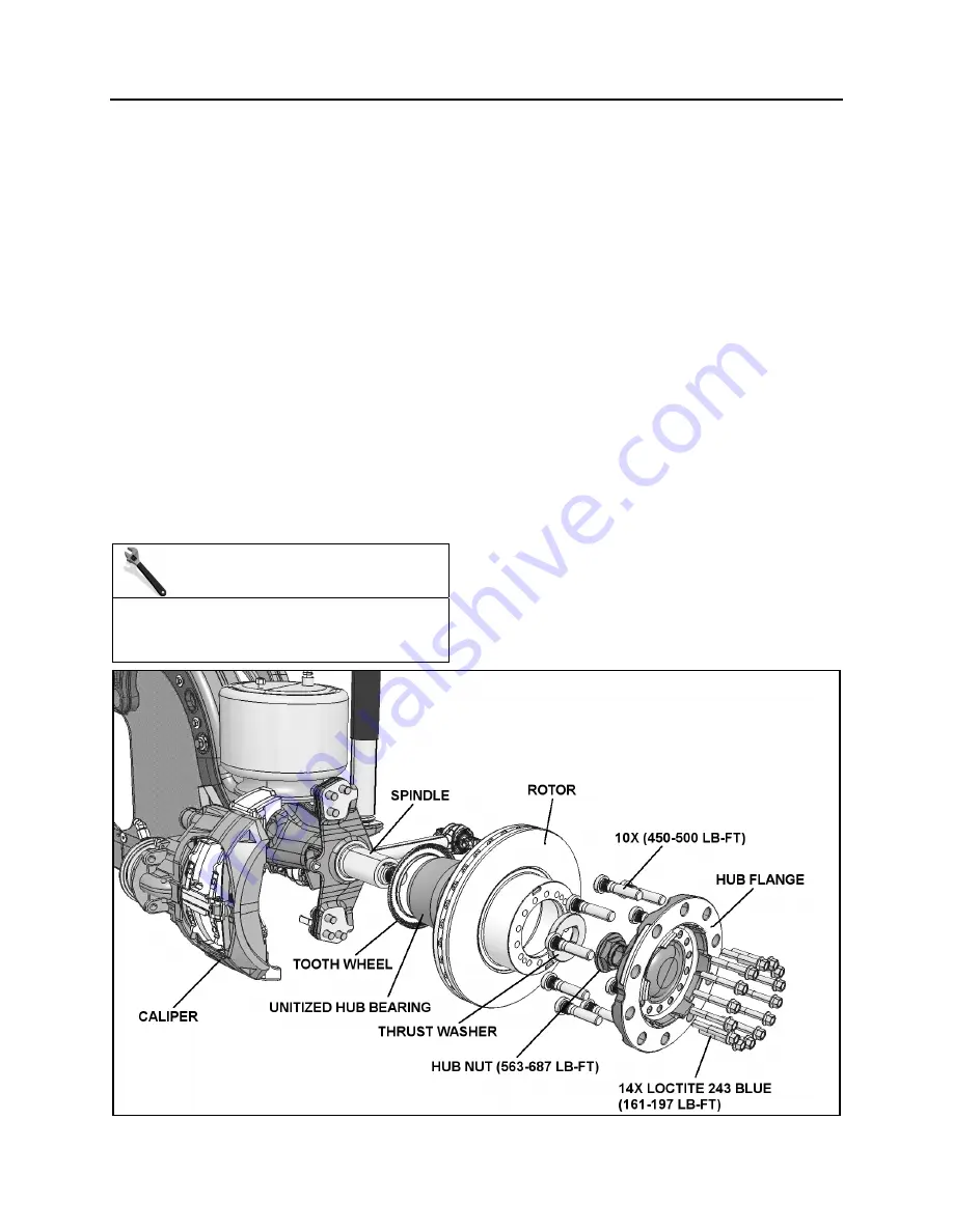
The unitized hub bearings used on the NDS
range of axles, are non-serviceable items.
Bearings are pre-adjusted, lubricated and have
seals fitted as part of the manufacturing process.
The bearings are greased for life and there is no
need or facility for re-lubrication
7.1 HUB BEARING INSPECTION
MAINTENANCE
An inspection should be made at intervals of
30,000 miles (48 000 km) or twice a year
whichever comes first.
Apply parking brake, raise wheels off the
ground and support axle on stands.
When the wheels are raised, they should
revolve quite freely without roughness.
Place magnetic base of a dial indicator on
brake caliper and position dial indicator stem
against a convenient marked spot on face of
hub flange.
With dial indicator in position pull hard but
steadily on hub flange and oscillate at same
time until a steady reading is achieved.
Without releasing the pressure, turn bearing
so that dial indicator stem contacts marked
spot and note reading on indicator.
Push bearing flange hard and oscillate as
before until a steady reading is achieved.
Without releasing the pressure, turn bearing
so that indicator stem again contacts the
marked spot and note new reading on
indicator.
The difference between readings is the
amount of mounted end play in bearing unit.
The mounted end play figure should not
exceed 0.004" (0.105mm) for a new bearing
in a used hub and 0.008" (0.20mm) for a
bearing which has been in service.
FIGURE 7: FRONT & TAG AXLE HUB AND ROTOR ASSEMBLY
Summary of Contents for X3-45 2016
Page 4: ......
Page 16: ...Section 00 GENERAL INFORMATION PA1593 12 FIGURE 12 METRIC US STANDARD CONVERSION TABLE 00005...
Page 17: ...Section 00 GENERAL INFORMATION 13 PA1593 FIGURE 13 CONVERSION CHART 00006...
Page 18: ......
Page 26: ......
Page 58: ......
Page 72: ...Section 04 EXHAUST AND AFTERTREATMENT SYSTEM PA1593 14 7 TORQUE SPECIFICATIONS...
Page 73: ...SECTION 04 EXHAUST AND AFTERTREATMENT SYSTEM PA1593 15...
Page 74: ...Section 04 EXHAUST AND AFTERTREATMENT SYSTEM PA1593 16...
Page 76: ......
Page 96: ......
Page 134: ......
Page 176: ...SECTION 06B ELECTRICAL 38 overcurrent working Circuit 306 shorted to ground...
Page 180: ......
Page 202: ......
Page 205: ...Section 09 PROPELLER SHAFT PA1593 3 FIGURE 1 PROPELLER SHAFT ASSEMBLY 09002...
Page 256: ......
Page 268: ......
Page 295: ...SECTION 16 SUSPENSION PA1593 9 2 5 TORQUE SPECIFICATIONS...
Page 296: ...Section 16 SUSPENSION PA1593 10...
Page 297: ...Section 16 SUSPENSION PA1593 11...
Page 314: ......
Page 380: ......
Page 388: ......
Page 413: ...Section 22 HEATING AND AIR CONDITIONING PA1593 15 FIGURE 18 REFRIGERANT CIRCUIT CENTRAL SYSTEM...
Page 433: ...Section 22 HEATING AND AIR CONDITIONING PA1593 35 FIGURE 36 CENTRAL HEATING SYSTEM COMPONENTS...


