Section 13: WHEELS, HUBS & TIRES
PA1593
9
9.1 INFLATION PRESSURE
The condition and pressure of the tires can
greatly affect both useful tire life and road safety.
At regular intervals, verify the tire pressures.
Use an accurate tire pressure gauge when
checking inflation pressures. Never exceed the
maximum inflation pressure specified on each
tire.
NOTE
Inflation pressure should be checked when
tires are cold. Cold tire inflation pressure can
be measured when a vehicle has not been
driven for at least 3 hours or less than 1 mile
(1.6 km). Driving, even for a short distance,
causes tires to heat up and air pressure to
increase. Check inflation pressure on all tires
(including the spare tire) using an accurate tire
gauge.
NOTE
The recommended tire inflation pressures are
given in the applicable documents supplied
with the vehicle. In addition, cold tire inflation
pressures are listed on the Department of
Transport's certification plate, affixed on the
panel behind the driver’s seat. For special tire
selection, a “PREVOST COACH SPECIAL
SPECIFICATION” chart is supplied with the
vehicle and is affixed on the left wall near the
driver’s seat. Remember, tire inflation
pressure must be adjusted according to
vehicle loading - see table in "Coach Final
Record"
CAUTION
Never bleed air from hot tires as tires will then
be under inflated. Use an accurate tire gauge
to check pressures (Do not kick tires as an
inflation check. This is an unreliable method).
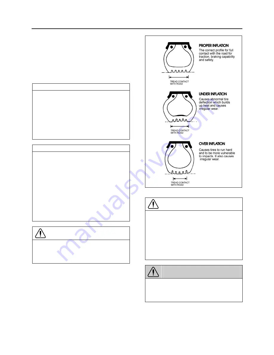
FIGURE 8: TIRE INFLATION
13009
CAUTION
These tire pressures are established in
accordance with the maximum allowable load
on each axle. A lower pressure is recom-
mended if the axle load is less than the above
specifications. Weigh vehicle fully loaded and
pressurize according to tire manufacturer's
recommendations. For other tire and wheel
specifications, see Prevost tire pressure
tabulation in "Coach Final Record".
WARNING
Incorrect tire pressures cause increased tire
wear and adversely affect road holding of the
vehicle, which may lead to loss of vehicle
control.
Summary of Contents for X3-45 2016
Page 4: ......
Page 16: ...Section 00 GENERAL INFORMATION PA1593 12 FIGURE 12 METRIC US STANDARD CONVERSION TABLE 00005...
Page 17: ...Section 00 GENERAL INFORMATION 13 PA1593 FIGURE 13 CONVERSION CHART 00006...
Page 18: ......
Page 26: ......
Page 58: ......
Page 72: ...Section 04 EXHAUST AND AFTERTREATMENT SYSTEM PA1593 14 7 TORQUE SPECIFICATIONS...
Page 73: ...SECTION 04 EXHAUST AND AFTERTREATMENT SYSTEM PA1593 15...
Page 74: ...Section 04 EXHAUST AND AFTERTREATMENT SYSTEM PA1593 16...
Page 76: ......
Page 96: ......
Page 134: ......
Page 176: ...SECTION 06B ELECTRICAL 38 overcurrent working Circuit 306 shorted to ground...
Page 180: ......
Page 202: ......
Page 205: ...Section 09 PROPELLER SHAFT PA1593 3 FIGURE 1 PROPELLER SHAFT ASSEMBLY 09002...
Page 256: ......
Page 268: ......
Page 295: ...SECTION 16 SUSPENSION PA1593 9 2 5 TORQUE SPECIFICATIONS...
Page 296: ...Section 16 SUSPENSION PA1593 10...
Page 297: ...Section 16 SUSPENSION PA1593 11...
Page 314: ......
Page 380: ......
Page 388: ......
Page 413: ...Section 22 HEATING AND AIR CONDITIONING PA1593 15 FIGURE 18 REFRIGERANT CIRCUIT CENTRAL SYSTEM...
Page 433: ...Section 22 HEATING AND AIR CONDITIONING PA1593 35 FIGURE 36 CENTRAL HEATING SYSTEM COMPONENTS...


