Section 14: STEERING
6
X3-45 Commuter PA1593 DOB 2400-2489
Section 14 Updated Oct.2014
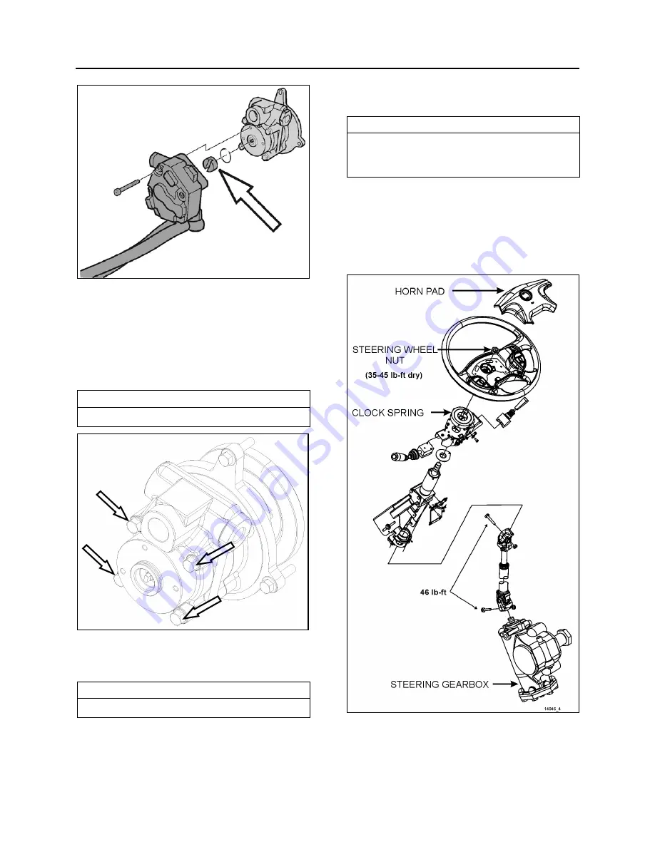
FIGURE 5: FUEL PUMP DRIVE AXLE
•
Set the fuel pump aside.
•
Clean around the power steering pump and
loosen the steering lines. Position a
container to catch any hydraulic fluid that
might drain from the pump or lines.
•
Unfasten the power steering pump bolts.
NOTE
Only unfasten the bolts marked with arrows.
FIGURE 6: POWER STEERING PUMP REMOVAL
•
Install the new power steering pump.
Torque-tighten bolts to specification.
NOTE
Use a new gasket.
•
Connect the hydraulic lines to the power
steering pump.
•
Install the fuel pump. Torque-tighten bolts to
specification.
NOTE
Use a new sealing ring. Check that the fuel
pump drive axle sits correctly in the power
steering pump.
•
Start the engine and let run for 5 minutes.
Make sure that there are no leaks.
6. STEERING COLUMN
6.1
REMOVAL
FIGURE 7: STEERING COLUMN
To disassemble the steering column from system,
refer to figure 7 & 8. The steering column has no
lubrication points. The lower steering column
Summary of Contents for X3-45 2016
Page 4: ......
Page 16: ...Section 00 GENERAL INFORMATION PA1593 12 FIGURE 12 METRIC US STANDARD CONVERSION TABLE 00005...
Page 17: ...Section 00 GENERAL INFORMATION 13 PA1593 FIGURE 13 CONVERSION CHART 00006...
Page 18: ......
Page 26: ......
Page 58: ......
Page 72: ...Section 04 EXHAUST AND AFTERTREATMENT SYSTEM PA1593 14 7 TORQUE SPECIFICATIONS...
Page 73: ...SECTION 04 EXHAUST AND AFTERTREATMENT SYSTEM PA1593 15...
Page 74: ...Section 04 EXHAUST AND AFTERTREATMENT SYSTEM PA1593 16...
Page 76: ......
Page 96: ......
Page 134: ......
Page 176: ...SECTION 06B ELECTRICAL 38 overcurrent working Circuit 306 shorted to ground...
Page 180: ......
Page 202: ......
Page 205: ...Section 09 PROPELLER SHAFT PA1593 3 FIGURE 1 PROPELLER SHAFT ASSEMBLY 09002...
Page 256: ......
Page 268: ......
Page 295: ...SECTION 16 SUSPENSION PA1593 9 2 5 TORQUE SPECIFICATIONS...
Page 296: ...Section 16 SUSPENSION PA1593 10...
Page 297: ...Section 16 SUSPENSION PA1593 11...
Page 314: ......
Page 380: ......
Page 388: ......
Page 413: ...Section 22 HEATING AND AIR CONDITIONING PA1593 15 FIGURE 18 REFRIGERANT CIRCUIT CENTRAL SYSTEM...
Page 433: ...Section 22 HEATING AND AIR CONDITIONING PA1593 35 FIGURE 36 CENTRAL HEATING SYSTEM COMPONENTS...


