Section 14: STEERING
Section 14 Updated Oct.2014
X3-45 Commuter PA1593 DOB 2400-2489
7
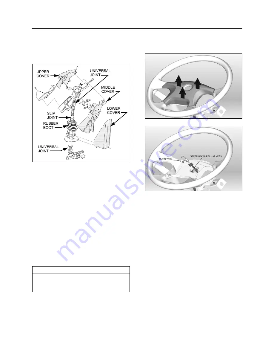
U-joint is easily accessible through the front
service compartment. The upper steering column
U-joint and the steering slip joint are accessible
from the front driver's area. To access these
joints, proceed as follows:
FIGURE 8: STEERING COLUMN COVERS
14040
1. From the front driver's compartment area,
remove the three plastic fasteners on steering
column lower cover. Remove the lower cover
(Fig. 8).
2. Unscrew the four retaining screws on steering
column middle cover.
3. Unscrew the four retaining screws fixing
steering column upper cover to middle cover.
Remove the steering column middle and
upper covers.
4. Position the steering wheel in order to gain
access to the joints.
7. STEERING WHEEL
7.1
REMOVAL
NOTE
Before undertaking the steering wheel removal,
assure that the front wheels are pointing straight
ahead, aligned with the vehicle.
1. Set the battery master switch located on the
rear electrical panel to the
"OFF"
position.
2. Pull the horn pad straight up gently to detach
it from the steering wheel (Fig. 9).
3. Disconnect the horn wire (white) connected to
the horn pad and the steering wheel harness
4-pin connector.
FIGURE 9: REMOVING THE HORN PAD
FIGURE 10: STEERING HARNESS & HORN WIRE
4. Unscrew the steering wheel nut. To simplify
installation and ensure steering wheel
alignment, mark the relationship of the spline
shaft to the steering wheel hub (if marks don’t
already exist or don’t line up).
5. Using an appropriate puller, separate the
steering wheel from the spline shaft.
6. From behind the steering wheel, pull gently on
the electrical wires passing through the
rectangular opening in the steering wheel to
finish removal of the steering wheel.
7. Once the steering wheel is removed, it is
important to block any rotating movement of
the clockspring in order to prevent it from
loosing its neutral position. Use two pieces of
masking tape to lock it in place (Fig. 11).
Summary of Contents for X3-45 2016
Page 4: ......
Page 16: ...Section 00 GENERAL INFORMATION PA1593 12 FIGURE 12 METRIC US STANDARD CONVERSION TABLE 00005...
Page 17: ...Section 00 GENERAL INFORMATION 13 PA1593 FIGURE 13 CONVERSION CHART 00006...
Page 18: ......
Page 26: ......
Page 58: ......
Page 72: ...Section 04 EXHAUST AND AFTERTREATMENT SYSTEM PA1593 14 7 TORQUE SPECIFICATIONS...
Page 73: ...SECTION 04 EXHAUST AND AFTERTREATMENT SYSTEM PA1593 15...
Page 74: ...Section 04 EXHAUST AND AFTERTREATMENT SYSTEM PA1593 16...
Page 76: ......
Page 96: ......
Page 134: ......
Page 176: ...SECTION 06B ELECTRICAL 38 overcurrent working Circuit 306 shorted to ground...
Page 180: ......
Page 202: ......
Page 205: ...Section 09 PROPELLER SHAFT PA1593 3 FIGURE 1 PROPELLER SHAFT ASSEMBLY 09002...
Page 256: ......
Page 268: ......
Page 295: ...SECTION 16 SUSPENSION PA1593 9 2 5 TORQUE SPECIFICATIONS...
Page 296: ...Section 16 SUSPENSION PA1593 10...
Page 297: ...Section 16 SUSPENSION PA1593 11...
Page 314: ......
Page 380: ......
Page 388: ......
Page 413: ...Section 22 HEATING AND AIR CONDITIONING PA1593 15 FIGURE 18 REFRIGERANT CIRCUIT CENTRAL SYSTEM...
Page 433: ...Section 22 HEATING AND AIR CONDITIONING PA1593 35 FIGURE 36 CENTRAL HEATING SYSTEM COMPONENTS...


