Section 14: STEERING
Section 14 Updated Oct.2014
X3-45 Commuter PA1593 DOB 2400-2489
11
power steering fluid reservoir.
If the steering linkage between the steering gear
and the two front wheels is not properly adjusted,
or if it is bent, twisted or worn, the steering of the
vehicle will be seriously impaired. Whenever a
steering linkage part is repaired, replaced or
adjusted, steering geometry and front wheel
alignment must be checked and necessary
corrections made. Refer to section 10
"Front Axle"
under heading 6:
"Front Wheel Alignment"
.
At regular lubrication intervals, the steering
linkage should be thoroughly inspected for worn or
loose components.
After the vehicle has been operated continually
and high mileage figures have been reached,
overhaul of the various steering units will be
required. General overhaul procedure normally
requires removal of the entire assembly, cleaning
and inspection of all parts and final assembly.
Careful inspection of all parts during overhaul is
very important and must not be neglected.
Lubrication fittings must all be cleaned before
applying lubricant. Moreover, always be sure the
equipment used in applying lubricant is clean.
Every precaution should be taken to prevent entry
of dirt, grit, lint or other foreign matter into lubricant
containers. Replace fittings that have become
broken or damaged. Lubrication intervals, as well
as the recommended lubricants for the steering
components, are given in the
"Lubrication And
Servicing Schedule"
in Section 24 of this manual.
The intervals given in the schedule are
recommended for normal service. More frequent
intervals may be required under severe operating
conditions.
11.1 POWER STEERING RESERVOIR AND
FILTER
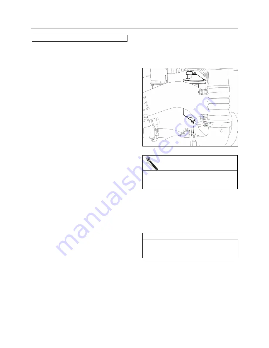
The power steering reservoir is located on R.H.
side of engine compartment and accessible
through the engine compartment doors. (Fig. 17).
11.1.1 Oil Level Check Procedure
1. Stop engine. Open engine compartment
doors.
2. Unscrew and remove the dipstick located on
top of reservoir and wipe with a clean rag.
3. Insert dipstick in reservoir. Remove it again to
check fluid level (Fig. 18).
4. Adjust level to
"FULL"
mark using proper
dipstick side depending on fluid temperature,
use
"Dexron-IIE or Dexron-III"
automatic
transmission oil.
5. Reinsert and tighten the dipstick.
6. At regular intervals, fluid level should be
checked in the reservoir and filter assembly.
FIGURE 17: HYDRAULIC FLUID RESERVOIR LOCATION
14059
MAINTENANCE
Replace the oil filter cartridge element in the
power steering reservoir every 50,000 miles (80
000 km) or once a year, whichever comes first.
11.1.2 Filter Replacement
1. Unscrew and remove the cover nut located on
top of the power steering reservoir.
2. Remove the reservoir cover and the gasket.
3. Remove the retaining spring and finally the
filter cartridge element.
NOTE
Power steering fluid reservoir is equipped with a
magnetic drain plug. Check for trapped metal
particle when replacing filter cartridge element.
Summary of Contents for X3-45 2016
Page 4: ......
Page 16: ...Section 00 GENERAL INFORMATION PA1593 12 FIGURE 12 METRIC US STANDARD CONVERSION TABLE 00005...
Page 17: ...Section 00 GENERAL INFORMATION 13 PA1593 FIGURE 13 CONVERSION CHART 00006...
Page 18: ......
Page 26: ......
Page 58: ......
Page 72: ...Section 04 EXHAUST AND AFTERTREATMENT SYSTEM PA1593 14 7 TORQUE SPECIFICATIONS...
Page 73: ...SECTION 04 EXHAUST AND AFTERTREATMENT SYSTEM PA1593 15...
Page 74: ...Section 04 EXHAUST AND AFTERTREATMENT SYSTEM PA1593 16...
Page 76: ......
Page 96: ......
Page 134: ......
Page 176: ...SECTION 06B ELECTRICAL 38 overcurrent working Circuit 306 shorted to ground...
Page 180: ......
Page 202: ......
Page 205: ...Section 09 PROPELLER SHAFT PA1593 3 FIGURE 1 PROPELLER SHAFT ASSEMBLY 09002...
Page 256: ......
Page 268: ......
Page 295: ...SECTION 16 SUSPENSION PA1593 9 2 5 TORQUE SPECIFICATIONS...
Page 296: ...Section 16 SUSPENSION PA1593 10...
Page 297: ...Section 16 SUSPENSION PA1593 11...
Page 314: ......
Page 380: ......
Page 388: ......
Page 413: ...Section 22 HEATING AND AIR CONDITIONING PA1593 15 FIGURE 18 REFRIGERANT CIRCUIT CENTRAL SYSTEM...
Page 433: ...Section 22 HEATING AND AIR CONDITIONING PA1593 35 FIGURE 36 CENTRAL HEATING SYSTEM COMPONENTS...


