Section 16: SUSPENSION
PA1593
3
1. DESCRIPTION
The vehicle is provided with an air suspension system. The system consists of air springs, height control
valves, radius rods, sway bars, tripod and shock absorbers. The system operation is fully automatic and
maintains a constant vehicle height regardless of load, or load distribution.
The vehicle is also equipped with this system:
Front
Kneeling;
2. I-BEAM AXLE FRONT SUSPENSION
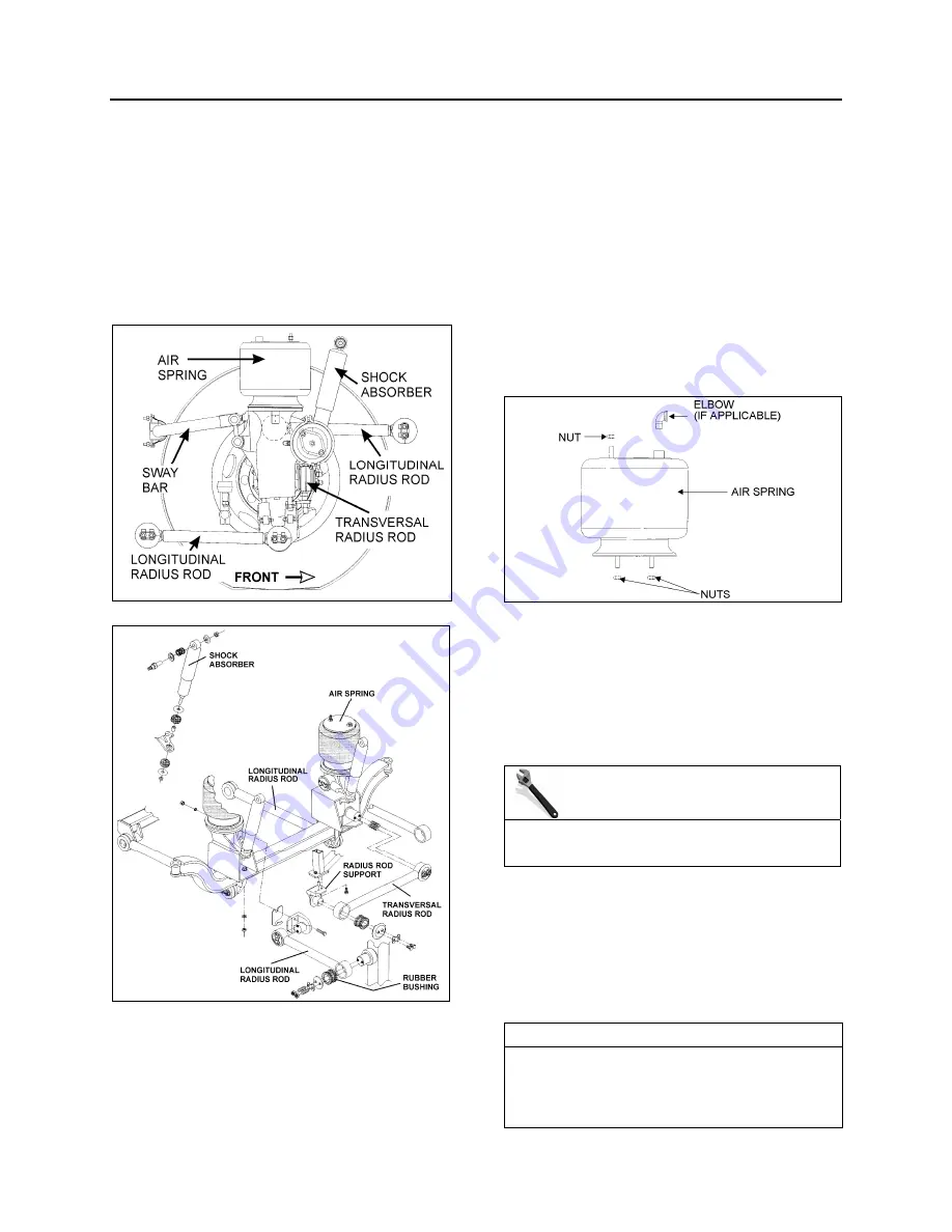
FIGURE 1: FRONT SUSPENSION COMPONENTS
16096
FIGURE 2: DETAILS OF FRONT SUSPENSION
16110
2.1 AIR
SPRINGS
The air springs are made from a special
compound rubber molded to the proper contour
and dimensions. The entire vertical load of the
vehicle is supported by these springs. The I-
beam front axle is provided with air springs that
are attached to the subframe and to the axle
(Fig. 3).
FIGURE 3: AIR SPRING
16052
2.1.1
Inspection
1. Check operation of bellows.
2. Visually inspect bellows for evidence of
cracks, punctures, deterioration, or chafing.
Replace the bellows if any damage is
evident.
MAINTENANCE
Inspect air bellows every 6,250 miles (10 000
km) or twice a year whichever comes first.
3. With the primary air system at normal
operating pressure (95 - 125 psi (655 - 860
kPa)), coat all suspension air line
connections and bellows mounting areas
with a water and soap solution. Bubbles will
indicate an air leak, and none is
permissible. Repair or replace defective
parts.
NOTE
If air spring is removed from vehicle, bellows
can be lightly inflated and submerged in water
to detect any leakage. If any leakage is
detected, replace bellows.
Summary of Contents for X3-45 2016
Page 4: ......
Page 16: ...Section 00 GENERAL INFORMATION PA1593 12 FIGURE 12 METRIC US STANDARD CONVERSION TABLE 00005...
Page 17: ...Section 00 GENERAL INFORMATION 13 PA1593 FIGURE 13 CONVERSION CHART 00006...
Page 18: ......
Page 26: ......
Page 58: ......
Page 72: ...Section 04 EXHAUST AND AFTERTREATMENT SYSTEM PA1593 14 7 TORQUE SPECIFICATIONS...
Page 73: ...SECTION 04 EXHAUST AND AFTERTREATMENT SYSTEM PA1593 15...
Page 74: ...Section 04 EXHAUST AND AFTERTREATMENT SYSTEM PA1593 16...
Page 76: ......
Page 96: ......
Page 134: ......
Page 176: ...SECTION 06B ELECTRICAL 38 overcurrent working Circuit 306 shorted to ground...
Page 180: ......
Page 202: ......
Page 205: ...Section 09 PROPELLER SHAFT PA1593 3 FIGURE 1 PROPELLER SHAFT ASSEMBLY 09002...
Page 256: ......
Page 268: ......
Page 295: ...SECTION 16 SUSPENSION PA1593 9 2 5 TORQUE SPECIFICATIONS...
Page 296: ...Section 16 SUSPENSION PA1593 10...
Page 297: ...Section 16 SUSPENSION PA1593 11...
Page 314: ......
Page 380: ......
Page 388: ......
Page 413: ...Section 22 HEATING AND AIR CONDITIONING PA1593 15 FIGURE 18 REFRIGERANT CIRCUIT CENTRAL SYSTEM...
Page 433: ...Section 22 HEATING AND AIR CONDITIONING PA1593 35 FIGURE 36 CENTRAL HEATING SYSTEM COMPONENTS...


