Section 16: SUSPENSION
PA1593
7
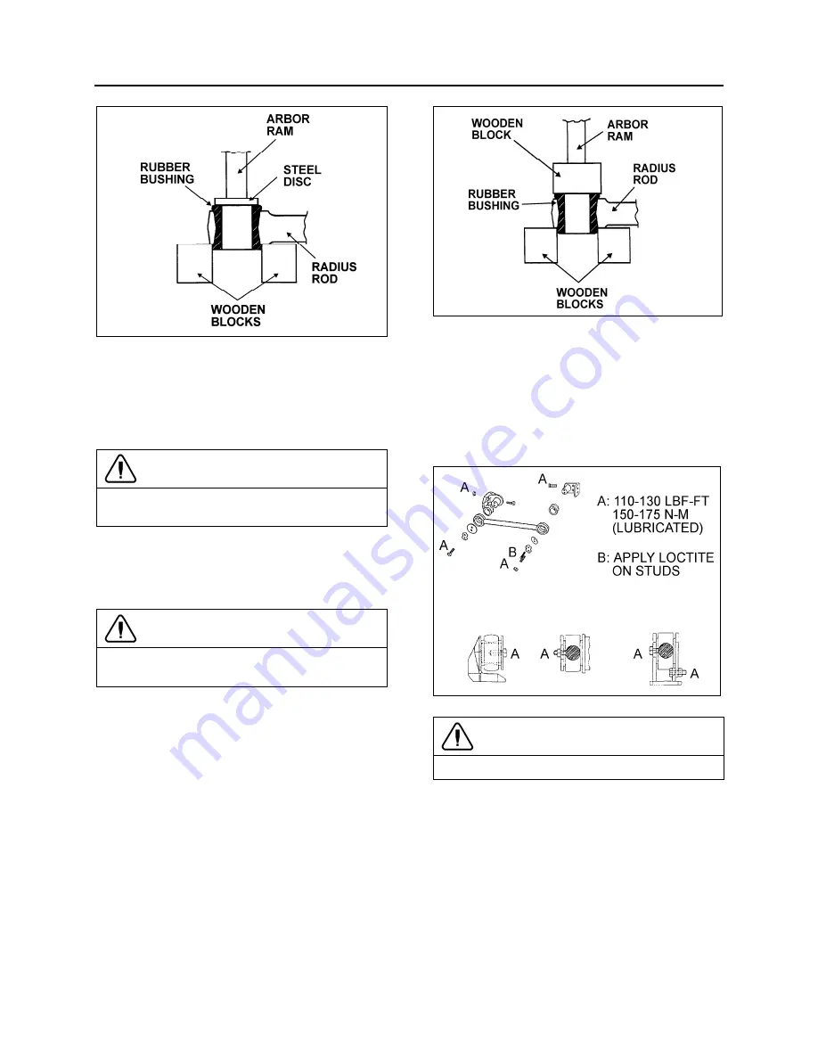
FIGURE 7: RADIUS ROD BUSHING REMOVAL
16011
2. Place a flat steel disc, slightly smaller than
the outside diameter of the bushing (Fig. 7).
3. Using an arbor press or a suitable driving
tool, press or drive the old bushing out of the
rod and discard the bushing.
CAUTION
Make sure to prevent the steel disc from
contacting the radius rod end.
2.3.4
Bushing installation
1. Lightly spray the inner and outer surfaces of
radius rod bushing with water.
CAUTION
No lubricant whatsoever is to be used on the
rubber bushing.
2. Safely support the radius rod, and place
new bushing on top of the radius rod end
(Fig. 8).
3. Place a block of wood on top of bushing and
press on it manually.
4. If necessary, use an arbor press or a suitable
driving tool. Press or drive the bushing into
the radius rod end until it extends equally on
both sides of the rod.
5. It is also possible to proceed differently.
Place radius rod bushing on a plane surface.
Spray a light coat of water on the inner and
outer surfaces of radius rod bushing.
6. Take radius rod, align the bushing. Tap
radius rod on bushing until latter is positioned
correctly.
FIGURE 8: RADIUS ROD BUSHING INSTALLATION
16012
2.3.5
Radius Rod Installation
1. Lightly spray the radius rod support with
water. Place the radius rod end over the
radius rod support (Fig. 9).
2. Position the retaining plate. Install the tab
washer and nuts (or bolts).
FIGURE 9: RADIUS ROD INSTALLATION
16028
CAUTION
Always use new tab washers at installation.
3. Tighten the nuts (or bolts) lightly, and repeat
at the other end.
4. Refer to heading
"Suspension Height
Adjustment"
later in this section, and set the
vehicle to normal ride height.
5. With the vehicle at normal ride height, apply
oil on threads and tighten all radius rod
anchor pin nuts or bolts to appropriate
torque (see Torque Table 1).
Summary of Contents for X3-45 2016
Page 4: ......
Page 16: ...Section 00 GENERAL INFORMATION PA1593 12 FIGURE 12 METRIC US STANDARD CONVERSION TABLE 00005...
Page 17: ...Section 00 GENERAL INFORMATION 13 PA1593 FIGURE 13 CONVERSION CHART 00006...
Page 18: ......
Page 26: ......
Page 58: ......
Page 72: ...Section 04 EXHAUST AND AFTERTREATMENT SYSTEM PA1593 14 7 TORQUE SPECIFICATIONS...
Page 73: ...SECTION 04 EXHAUST AND AFTERTREATMENT SYSTEM PA1593 15...
Page 74: ...Section 04 EXHAUST AND AFTERTREATMENT SYSTEM PA1593 16...
Page 76: ......
Page 96: ......
Page 134: ......
Page 176: ...SECTION 06B ELECTRICAL 38 overcurrent working Circuit 306 shorted to ground...
Page 180: ......
Page 202: ......
Page 205: ...Section 09 PROPELLER SHAFT PA1593 3 FIGURE 1 PROPELLER SHAFT ASSEMBLY 09002...
Page 256: ......
Page 268: ......
Page 295: ...SECTION 16 SUSPENSION PA1593 9 2 5 TORQUE SPECIFICATIONS...
Page 296: ...Section 16 SUSPENSION PA1593 10...
Page 297: ...Section 16 SUSPENSION PA1593 11...
Page 314: ......
Page 380: ......
Page 388: ......
Page 413: ...Section 22 HEATING AND AIR CONDITIONING PA1593 15 FIGURE 18 REFRIGERANT CIRCUIT CENTRAL SYSTEM...
Page 433: ...Section 22 HEATING AND AIR CONDITIONING PA1593 35 FIGURE 36 CENTRAL HEATING SYSTEM COMPONENTS...


