Section 16: SUSPENSION
PA1593
17
FIGURE 17: TYPICAL SHOCK ABSORBER SETUP
16009
5. Place the lower and upper mounting pin
stud nuts and torque to 70 - 80 lbf-ft (95 –
110 Nm).
3.3 RADIUS
RODS
Radius rods are used to secure the axles in the
proper transversal and longitudinal positions.
Four radius rods are provided on the drive axle
suspension (three longitudinal and one
transversal) and also four on the tag axle with a
layout similar to the drive axle. Refer to figures
13, 14 and 18 for details. These rods transmit
both braking and driving forces from the axles to
the vehicle body.
3.3.1
Rear Underframe Suspension
FIGURE 18: TYPICAL RADIUS ROD SETUP
16010
Radius Rod Inspection
The following instructions apply to the radius
rods used on the rear underframe suspension:
1. Clean all parts thoroughly.
2. Inspect radius rods for distortion and cracks.
We recommend the “Magnaflux” process to
detect cracks in the radius rod. Any
damaged part should be replaced with a
new one.
NOTE
New bushings should be used when rods are
replaced.
3. The radius rod bushings should be checked
periodically for signs of shearing,
deterioration, or damage. Any defective part
should be replaced with a new one.
Radius Rod Removal
1. Flatten the tab washer which secures the
two retaining nuts (or bolts), then unscrew
the nuts (or bolts) at each extremity of the
radius rod (Fig. 19).
2. Remove the tab washer and the retaining
plates and radius rod ends from anchor
pins, and then remove the radius rod.
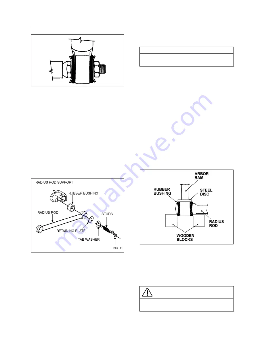
Bushing removal
1. Safely support the radius rod as shown in
figure 19.
FIGURE 19: RADIUS ROD BUSHING REMOVAL
16011
2. Place a flat steel disc, slightly smaller than
the outside diameter of the bushing (Fig.
19).
3. Using an arbor press or a suitable driving
tool, press or drive the old bushing out of the
rod and discard the bushing.
CAUTION
Make sure to prevent the steel disc from
contacting the radius rod end.
Summary of Contents for X3-45 2016
Page 4: ......
Page 16: ...Section 00 GENERAL INFORMATION PA1593 12 FIGURE 12 METRIC US STANDARD CONVERSION TABLE 00005...
Page 17: ...Section 00 GENERAL INFORMATION 13 PA1593 FIGURE 13 CONVERSION CHART 00006...
Page 18: ......
Page 26: ......
Page 58: ......
Page 72: ...Section 04 EXHAUST AND AFTERTREATMENT SYSTEM PA1593 14 7 TORQUE SPECIFICATIONS...
Page 73: ...SECTION 04 EXHAUST AND AFTERTREATMENT SYSTEM PA1593 15...
Page 74: ...Section 04 EXHAUST AND AFTERTREATMENT SYSTEM PA1593 16...
Page 76: ......
Page 96: ......
Page 134: ......
Page 176: ...SECTION 06B ELECTRICAL 38 overcurrent working Circuit 306 shorted to ground...
Page 180: ......
Page 202: ......
Page 205: ...Section 09 PROPELLER SHAFT PA1593 3 FIGURE 1 PROPELLER SHAFT ASSEMBLY 09002...
Page 256: ......
Page 268: ......
Page 295: ...SECTION 16 SUSPENSION PA1593 9 2 5 TORQUE SPECIFICATIONS...
Page 296: ...Section 16 SUSPENSION PA1593 10...
Page 297: ...Section 16 SUSPENSION PA1593 11...
Page 314: ......
Page 380: ......
Page 388: ......
Page 413: ...Section 22 HEATING AND AIR CONDITIONING PA1593 15 FIGURE 18 REFRIGERANT CIRCUIT CENTRAL SYSTEM...
Page 433: ...Section 22 HEATING AND AIR CONDITIONING PA1593 35 FIGURE 36 CENTRAL HEATING SYSTEM COMPONENTS...


