Section 16: SUSPENSION
PA1593
19
The assembly work may be done only by a
recognized specialized workshop. Ensure that
old and new parts do not get mixed up with each
other. It is for this reason that all the old parts
are to be scrapped immediately after a joint has
been stripped down. A complete repair set must
be used for each joint repaired, i.e. use of only
part of a repair set is not permissible.
Radius Rod Inspection
Take off the load from the ball joint by lifting the
rear of the vehicle. Apply a load on the joint in all
of the degrees of freedom in an axial, radial, etc.
sense with a suitable lever tool. After the load is
taken off, the joint has to spring back into its
starting position. Free play is not acceptable.
Separation of rubber from ball pin or external
joint shell is in accordance with "normal wear
characteristics".
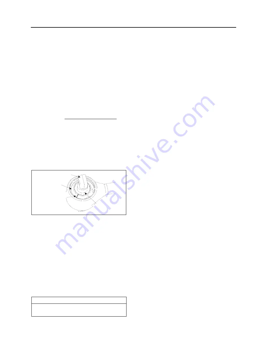
When the following characteristics are noted, the
joint is to be changed:
Free play;
Radial cracking of the external sheet-metal
race.
Ball pin
External joint shell
Radial cracking of the
sheet-metal race
Partial separation
is permitted
FIGURE 23: BALL JOINTS
16173
Stripping Down
Strip down the defective joint through removal of
retaining ring, annular spacer and ball
pin/bushing, assembly and thereafter clean out
housing bore and locking circlips groove.
Radius Rod Assembly
Execute assembly of the new joint parts in the
following sequence:
1. Complete moistening of the contact surface
between housing bore and ball pin through
application of the grease.
NOTE
Apply grease, only in the case of repair kit
(Prevost # 611114)).
2. Insert ball pin/bushing, assembly. In case of
the two-bolt type, ensure that the bolt bores
are in the correct position in relation to the
axis of the tube.
3. Place joint in receiving fixture and mount
annular assembly tool on the housing. Then
locate annular spacer and retaining ring in
the housing using axial load with the aid of
assembly matrix. If the ends of the annular
spacer are not in contact with each other,
the thus formed opening must be located at
180
to the opening of the retaining ring. Pay
attention during assembly to ensure that the
retaining ring eyelets are located at each
side of the housing shaft axis (retaining ring
eyelet lug points to tube), and that retaining
ring is properly engaged in the groove of the
housing.
When repairing defective ball pin assemblies,
the necked down-bolt must regularly be replaced
with a new one.
Summary of Contents for X3-45 2016
Page 4: ......
Page 16: ...Section 00 GENERAL INFORMATION PA1593 12 FIGURE 12 METRIC US STANDARD CONVERSION TABLE 00005...
Page 17: ...Section 00 GENERAL INFORMATION 13 PA1593 FIGURE 13 CONVERSION CHART 00006...
Page 18: ......
Page 26: ......
Page 58: ......
Page 72: ...Section 04 EXHAUST AND AFTERTREATMENT SYSTEM PA1593 14 7 TORQUE SPECIFICATIONS...
Page 73: ...SECTION 04 EXHAUST AND AFTERTREATMENT SYSTEM PA1593 15...
Page 74: ...Section 04 EXHAUST AND AFTERTREATMENT SYSTEM PA1593 16...
Page 76: ......
Page 96: ......
Page 134: ......
Page 176: ...SECTION 06B ELECTRICAL 38 overcurrent working Circuit 306 shorted to ground...
Page 180: ......
Page 202: ......
Page 205: ...Section 09 PROPELLER SHAFT PA1593 3 FIGURE 1 PROPELLER SHAFT ASSEMBLY 09002...
Page 256: ......
Page 268: ......
Page 295: ...SECTION 16 SUSPENSION PA1593 9 2 5 TORQUE SPECIFICATIONS...
Page 296: ...Section 16 SUSPENSION PA1593 10...
Page 297: ...Section 16 SUSPENSION PA1593 11...
Page 314: ......
Page 380: ......
Page 388: ......
Page 413: ...Section 22 HEATING AND AIR CONDITIONING PA1593 15 FIGURE 18 REFRIGERANT CIRCUIT CENTRAL SYSTEM...
Page 433: ...Section 22 HEATING AND AIR CONDITIONING PA1593 35 FIGURE 36 CENTRAL HEATING SYSTEM COMPONENTS...


