Section 18: BODY
PA1593
15
6.
X3-45 COACHES EXTERIOR FINISHING AND BODY REPAIR
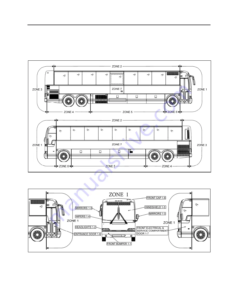
The following procedures explain the steps to be followed for proper repair, installation and replacement
for various doors, panels and windows. The paragraph divides the vehicle into zones to facilitate the
search; each zone is then sub-divided into components.
Refer to the appropriate zone then component for complete procedure.
FIGURE 7: X3 COACHES ZONING
18623
6.1 ZONE
1
FIGURE 8: ZONE 1
18624
6.1.1 Front
Bumper
The front bumper is hinged to give access to the
steering gear and front towing quick connectors
for maintenance purposes. Pull the handle
located in the front service compartment to open
the front bumper compartment. Bumper must
first be tilted down before its removal. Two
people are required to remove and install the
front bumper. Safely support the bumper and
Summary of Contents for X3-45 2016
Page 4: ......
Page 16: ...Section 00 GENERAL INFORMATION PA1593 12 FIGURE 12 METRIC US STANDARD CONVERSION TABLE 00005...
Page 17: ...Section 00 GENERAL INFORMATION 13 PA1593 FIGURE 13 CONVERSION CHART 00006...
Page 18: ......
Page 26: ......
Page 58: ......
Page 72: ...Section 04 EXHAUST AND AFTERTREATMENT SYSTEM PA1593 14 7 TORQUE SPECIFICATIONS...
Page 73: ...SECTION 04 EXHAUST AND AFTERTREATMENT SYSTEM PA1593 15...
Page 74: ...Section 04 EXHAUST AND AFTERTREATMENT SYSTEM PA1593 16...
Page 76: ......
Page 96: ......
Page 134: ......
Page 176: ...SECTION 06B ELECTRICAL 38 overcurrent working Circuit 306 shorted to ground...
Page 180: ......
Page 202: ......
Page 205: ...Section 09 PROPELLER SHAFT PA1593 3 FIGURE 1 PROPELLER SHAFT ASSEMBLY 09002...
Page 256: ......
Page 268: ......
Page 295: ...SECTION 16 SUSPENSION PA1593 9 2 5 TORQUE SPECIFICATIONS...
Page 296: ...Section 16 SUSPENSION PA1593 10...
Page 297: ...Section 16 SUSPENSION PA1593 11...
Page 314: ......
Page 380: ......
Page 388: ......
Page 413: ...Section 22 HEATING AND AIR CONDITIONING PA1593 15 FIGURE 18 REFRIGERANT CIRCUIT CENTRAL SYSTEM...
Page 433: ...Section 22 HEATING AND AIR CONDITIONING PA1593 35 FIGURE 36 CENTRAL HEATING SYSTEM COMPONENTS...


