Section 18: BODY
PA1593
19
Spray filler and rubber seal groove
generously with soapy water.
Using the special filler insertion tool, insert
the filler into the rubber seal groove.
Gradually insert filler into the rubber seal
groove ensuring to leave a 2 inch excess
length at the filler extremity.
Every 6 inches or so, it is important to
compress the filler due to its tendency to
contract during drying process.
When filler insertion is almost complete,
cut filler leaving ¼” of excess length to
thwart filler contraction over time then
insert filler into groove.
FIGURE 15: APPLICATION 0F SIKA 221 BLACK
Reinstall center post and interior finishing
panels.
Clean windshield surface of butyl residue.
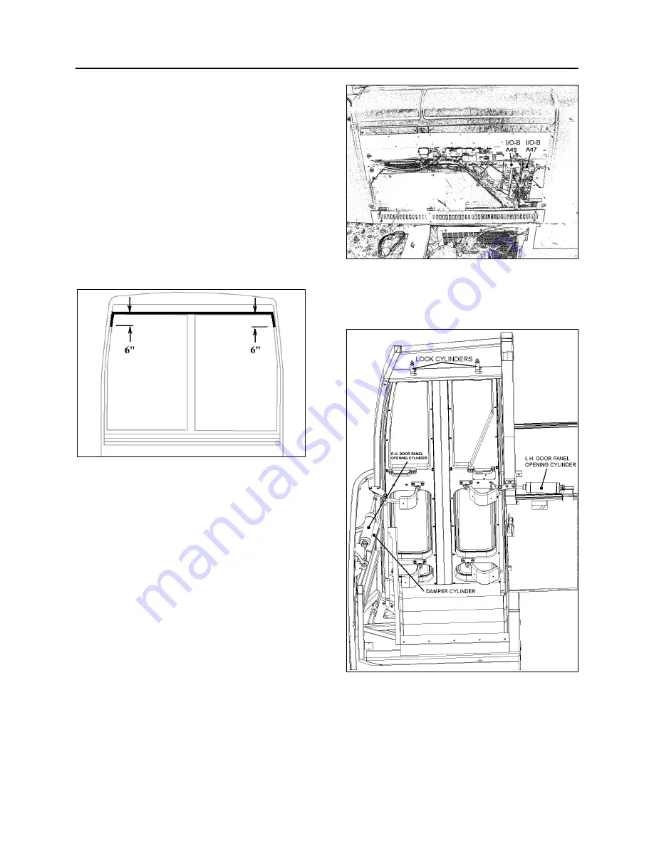
6.1.6 Bi-Fold Entrance Door
An air operated “bi-fold type” entrance door, with
an air door cylinder and damper assembly
installed under the right hand dash for the R.H.
door panel opening. Another air door cylinder is
installed behind the wall to the right of the first
curb-side passengers’ seat for the L.H. door
panel opening. The opening and closing door
speed cycle is adjustable by a damper mounted
in parallel with the R.H. door panel cylinder on
the door hinge. Door activation is controlled by a
panel (Fig. 16), located near the defroster and
wiper motors. The accessory air reservoir
supplies air to this system.
FIGURE 16: ENTRANCE DOOR & WIPER CONTROL
PANEL
06619
The door is held in the closed position during
coach operation by a two air cylinder locking
mechanisms (Fig. 17).
FIGURE 17: ENTRANCE DOOR - VIEW FROM INSIDE
Air cylinders with return spring in the cylinder
body are used. Air cylinders are controlled by an
electrically operated solenoid valve energized by
a multiplex module located under the right hand
dashboard.
Summary of Contents for X3-45 2016
Page 4: ......
Page 16: ...Section 00 GENERAL INFORMATION PA1593 12 FIGURE 12 METRIC US STANDARD CONVERSION TABLE 00005...
Page 17: ...Section 00 GENERAL INFORMATION 13 PA1593 FIGURE 13 CONVERSION CHART 00006...
Page 18: ......
Page 26: ......
Page 58: ......
Page 72: ...Section 04 EXHAUST AND AFTERTREATMENT SYSTEM PA1593 14 7 TORQUE SPECIFICATIONS...
Page 73: ...SECTION 04 EXHAUST AND AFTERTREATMENT SYSTEM PA1593 15...
Page 74: ...Section 04 EXHAUST AND AFTERTREATMENT SYSTEM PA1593 16...
Page 76: ......
Page 96: ......
Page 134: ......
Page 176: ...SECTION 06B ELECTRICAL 38 overcurrent working Circuit 306 shorted to ground...
Page 180: ......
Page 202: ......
Page 205: ...Section 09 PROPELLER SHAFT PA1593 3 FIGURE 1 PROPELLER SHAFT ASSEMBLY 09002...
Page 256: ......
Page 268: ......
Page 295: ...SECTION 16 SUSPENSION PA1593 9 2 5 TORQUE SPECIFICATIONS...
Page 296: ...Section 16 SUSPENSION PA1593 10...
Page 297: ...Section 16 SUSPENSION PA1593 11...
Page 314: ......
Page 380: ......
Page 388: ......
Page 413: ...Section 22 HEATING AND AIR CONDITIONING PA1593 15 FIGURE 18 REFRIGERANT CIRCUIT CENTRAL SYSTEM...
Page 433: ...Section 22 HEATING AND AIR CONDITIONING PA1593 35 FIGURE 36 CENTRAL HEATING SYSTEM COMPONENTS...


