Section 18: BODY
PA1593
20
To open the door, initial action from multiplex
module output de-energizes the air lock solenoid
valve, venting the door locking cylinders. The
return locking spring pulls the door lock away
from the latch, unlocking the door. Door
movement starts only when pressure in the
central air door lock is below 10 psi. The “air
cylinder open solenoid valve” opens and allows
air to flow to the door cylinders, “the air cylinder
close solenoid valve” exhausts air from the rod
side of the cylinders.
To close the door, initial movement of the switch
energizes the “air cylinder close solenoid valve”
and air flows to the cylinders by their rod side
ports. The “air cylinder open solenoid valve”
exhausts air from cylinders. When entrance door
latch is grounded with the door frame, the air
lock solenoid valve is de-energized and loads
the door lock cylinders. The cylinder moves the
door lock in a position which engages a latch on
the entrance door, holding the door positively
closed.
Emergency exit valve, which opens the air valve
circuit should be used only in emergencies, or
when the door control system does not function
properly.
Refer to the air system schematic diagram
annexed at the end of section 12, “Brakes” and
to page 29.1 of the wiring diagram.
Operation
Lock or unlock the bi-fold entrance door from
outside the vehicle by turning the key in the door
lock (counterclockwise to lock, clockwise to
unlock). The entrance door can be unlocked
from the inside using the small lever located on
the door.
The air-operated door is controlled from inside
the coach by two push-button switches located
on the R.H. dashboard.
FIGURE 18: ENTRANCE DOOR OPERATING BUTTONS
06464
From the inside, open the door by pressing the
door opening switch (L.H. button) on the R.H.
dashboard panel. The door will open to full open
position within 5 seconds.
Close by pressing and holding the door closing
switch (R.H. button) on the dashboard. If the
closing switch is released before the door is fully
closed, the door will stop in that position.
FIGURE 19: ENTRANCE DOOR CONTROL SWITCH
18599
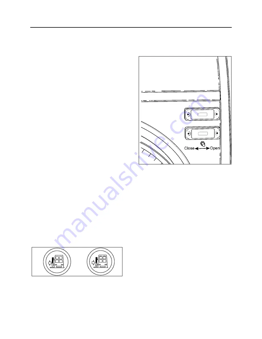
Opening and closing of the door from outside
the coach is accomplished by a momentary
toggle switch located under the front R.H. side
marker light (Fig. 19).
To close the door, the switch must be pushed
towards the rear of the coach and held in
position until the door has completed its
movement. The door can be closed to any
position by releasing the switch (or button, if
inside) when the desired position is attained.
However, the door is not locked in any position
other than fully closed. The door can then be
closed further by pushing or pulling on the door.
To open the door, the switch must be pushed
towards the front of the coach and held in
position. When the door reaches the fully
opened position, the system will keep pressure
in the cylinder locking the door in that position.
Summary of Contents for X3-45 2016
Page 4: ......
Page 16: ...Section 00 GENERAL INFORMATION PA1593 12 FIGURE 12 METRIC US STANDARD CONVERSION TABLE 00005...
Page 17: ...Section 00 GENERAL INFORMATION 13 PA1593 FIGURE 13 CONVERSION CHART 00006...
Page 18: ......
Page 26: ......
Page 58: ......
Page 72: ...Section 04 EXHAUST AND AFTERTREATMENT SYSTEM PA1593 14 7 TORQUE SPECIFICATIONS...
Page 73: ...SECTION 04 EXHAUST AND AFTERTREATMENT SYSTEM PA1593 15...
Page 74: ...Section 04 EXHAUST AND AFTERTREATMENT SYSTEM PA1593 16...
Page 76: ......
Page 96: ......
Page 134: ......
Page 176: ...SECTION 06B ELECTRICAL 38 overcurrent working Circuit 306 shorted to ground...
Page 180: ......
Page 202: ......
Page 205: ...Section 09 PROPELLER SHAFT PA1593 3 FIGURE 1 PROPELLER SHAFT ASSEMBLY 09002...
Page 256: ......
Page 268: ......
Page 295: ...SECTION 16 SUSPENSION PA1593 9 2 5 TORQUE SPECIFICATIONS...
Page 296: ...Section 16 SUSPENSION PA1593 10...
Page 297: ...Section 16 SUSPENSION PA1593 11...
Page 314: ......
Page 380: ......
Page 388: ......
Page 413: ...Section 22 HEATING AND AIR CONDITIONING PA1593 15 FIGURE 18 REFRIGERANT CIRCUIT CENTRAL SYSTEM...
Page 433: ...Section 22 HEATING AND AIR CONDITIONING PA1593 35 FIGURE 36 CENTRAL HEATING SYSTEM COMPONENTS...


