Section 18: BODY
PA1593
21
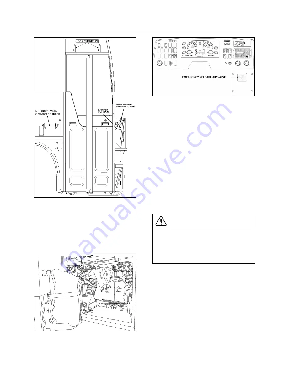
FIGURE 20: ENTRANCE DOOR - VIEW FROM OUTSIDE
Emergency Exit Valves
From inside the vehicle, an emergency exit
valve located on the dashboard R.H. side,
releases the pressure from the lock cylinders.
From the exterior, an emergency exit valve
located in the front service compartment, also
releases the air from the lock cylinders.
FIGURE 21: EXTERIOR UNLATCH AIR VALVE
12209
FIGURE 22: INTERIOR UNLATCH AIR VALVE
18330
Without Air and/or Without Electricity
If the air pressure drops while the coach has or
hasn’t any electricity, the spring loaded cylinders
will unlatch the door. In such a case, unlock the
door by moving the lever on the door or by using
the key, then open the door manually.
With Air but Without Electricity
From inside the vehicle, turn the emergency exit
valve to the "UNLOCK” position. Move the lever.
From the exterior, turn the emergency exit valve
to the “UNLOCK” position. Open the door. Close
it, lock with the key and reset the outside
emergency exit valve to the “NORMAL” position.
Door Cycle Speed Adjustment
To do any adjustment, remove the panels
located next to the R.H door panel hinges.
CAUTION
It is important to make sure that damper does
not reach end of stroke when bi-fold entrance
door is completely closed or opened. The door
cylinders must stop the door on opening.
Screw or unscrew rod end to adjust if
necessary.
To adjust opening and closing cycle speed on
damper (Fig. 23):
1. Remove the damper from the vehicle and
hold it vertically with the lower eye or pin
attachment in a vice. Use clamp plates to
prevent damage.
2. Fully close the damper while turning the
dust cap or piston rod slowly CCW until it is
felt that the cams of the adjusting nut
engage in the recesses of the foot valve
assembly (Fig. 23).
Summary of Contents for X3-45 2016
Page 4: ......
Page 16: ...Section 00 GENERAL INFORMATION PA1593 12 FIGURE 12 METRIC US STANDARD CONVERSION TABLE 00005...
Page 17: ...Section 00 GENERAL INFORMATION 13 PA1593 FIGURE 13 CONVERSION CHART 00006...
Page 18: ......
Page 26: ......
Page 58: ......
Page 72: ...Section 04 EXHAUST AND AFTERTREATMENT SYSTEM PA1593 14 7 TORQUE SPECIFICATIONS...
Page 73: ...SECTION 04 EXHAUST AND AFTERTREATMENT SYSTEM PA1593 15...
Page 74: ...Section 04 EXHAUST AND AFTERTREATMENT SYSTEM PA1593 16...
Page 76: ......
Page 96: ......
Page 134: ......
Page 176: ...SECTION 06B ELECTRICAL 38 overcurrent working Circuit 306 shorted to ground...
Page 180: ......
Page 202: ......
Page 205: ...Section 09 PROPELLER SHAFT PA1593 3 FIGURE 1 PROPELLER SHAFT ASSEMBLY 09002...
Page 256: ......
Page 268: ......
Page 295: ...SECTION 16 SUSPENSION PA1593 9 2 5 TORQUE SPECIFICATIONS...
Page 296: ...Section 16 SUSPENSION PA1593 10...
Page 297: ...Section 16 SUSPENSION PA1593 11...
Page 314: ......
Page 380: ......
Page 388: ......
Page 413: ...Section 22 HEATING AND AIR CONDITIONING PA1593 15 FIGURE 18 REFRIGERANT CIRCUIT CENTRAL SYSTEM...
Page 433: ...Section 22 HEATING AND AIR CONDITIONING PA1593 35 FIGURE 36 CENTRAL HEATING SYSTEM COMPONENTS...


