Section 18: BODY
PA1593
23
o
Depth adjustment
1. Support the door panel with a wooden block
and a hydraulic jack.
2. Unfasten and then disconnect rod ends from
door panel fixing plates. Screw or unscrew
rod end in order to adjust door panel depth.
3. Tighten the bolts. Remove the jack and the
wooden block
6.1.7 Front
Electrical
& Service Compartment
Door
Door adjustment
Check around the perimeter of the door for
binding. If any binding is found, adjust as
follows:
1. Remove the screws and the plastic molding
covering each of the hinges.
NOTE
Ask an assistant to help you to perform the
following adjustments.
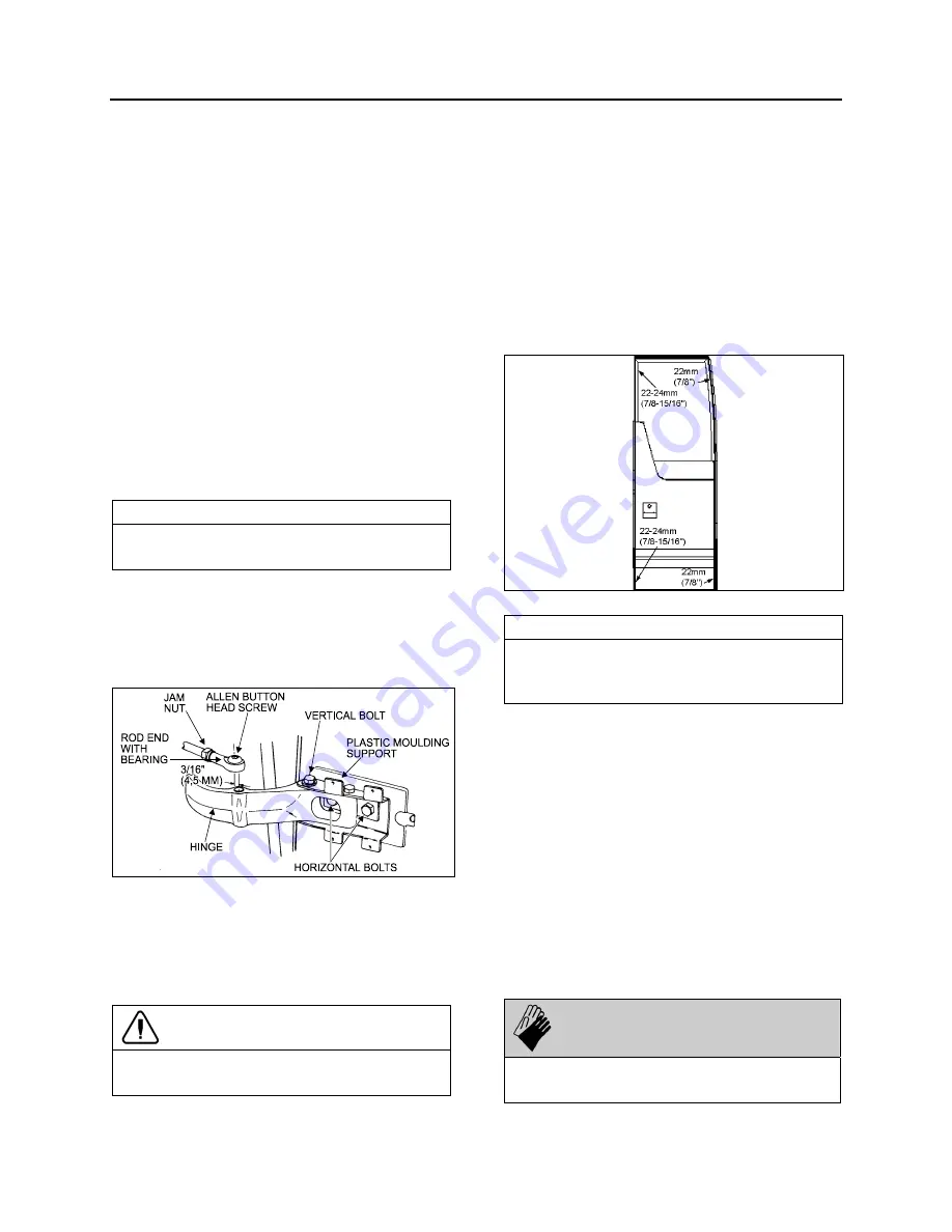
2. Remove the Allen button head screw and
the washer retaining the rod end with bear-
ing to the upper hinge. See figure 25.
3. Support the door with a wooden block and a
hydraulic jack.
FIGURE 25: UPPER DOOR HINGE
18058
4. Loosen the horizontal bolts retaining the
door to the hinges. Adjust the door horizon-
tally and vertically with the jack. Tighten the
bolts to 30-36 Lbf-ft (40-50 Nm). Remove
the jack and the wooden block.
CAUTION
Make sure the front side door does not
interfere with the exterior panel.
5. Pull and fasten the rod end to the hinge with
the washer and the button screw.
6. Screw the plastic moldings covering the
hinges.
Seal Compression Adjustment
1. From the outside of vehicle, insert a straight
edge in the gap along the door outside
perimeter. Measure the distance between
the door frame and the door outside surface
at the door four corners (refer to figure 26).
FIGURE 26: SEAL COMPRESSION ADJUSTMENT
18632
NOTE
The front measurements are the most
important. If required, ask an assistant to help
you to perform the following adjustments.
2. If required loosen the bolts retaining the
door to the hinges. Adjust the bolts to obtain
the proper seal compression.
Door Seal Replacement
1. Inspect the seal; if cracked or torn, it must
be replaced:
2. Remove the old seal and with a sharp edge
knife, scrape tape left on the fiberglass door
surface.
3. Sand the surface of the door where a new
seal will be applied with 240 grit sandpaper.
4. Clean the surface with alcohol.
WARNING
Wear rubber gloves and do not smoke when
cleaning.
Summary of Contents for X3-45 2016
Page 4: ......
Page 16: ...Section 00 GENERAL INFORMATION PA1593 12 FIGURE 12 METRIC US STANDARD CONVERSION TABLE 00005...
Page 17: ...Section 00 GENERAL INFORMATION 13 PA1593 FIGURE 13 CONVERSION CHART 00006...
Page 18: ......
Page 26: ......
Page 58: ......
Page 72: ...Section 04 EXHAUST AND AFTERTREATMENT SYSTEM PA1593 14 7 TORQUE SPECIFICATIONS...
Page 73: ...SECTION 04 EXHAUST AND AFTERTREATMENT SYSTEM PA1593 15...
Page 74: ...Section 04 EXHAUST AND AFTERTREATMENT SYSTEM PA1593 16...
Page 76: ......
Page 96: ......
Page 134: ......
Page 176: ...SECTION 06B ELECTRICAL 38 overcurrent working Circuit 306 shorted to ground...
Page 180: ......
Page 202: ......
Page 205: ...Section 09 PROPELLER SHAFT PA1593 3 FIGURE 1 PROPELLER SHAFT ASSEMBLY 09002...
Page 256: ......
Page 268: ......
Page 295: ...SECTION 16 SUSPENSION PA1593 9 2 5 TORQUE SPECIFICATIONS...
Page 296: ...Section 16 SUSPENSION PA1593 10...
Page 297: ...Section 16 SUSPENSION PA1593 11...
Page 314: ......
Page 380: ......
Page 388: ......
Page 413: ...Section 22 HEATING AND AIR CONDITIONING PA1593 15 FIGURE 18 REFRIGERANT CIRCUIT CENTRAL SYSTEM...
Page 433: ...Section 22 HEATING AND AIR CONDITIONING PA1593 35 FIGURE 36 CENTRAL HEATING SYSTEM COMPONENTS...


