Section 18: BODY
PA1593
55
6.10.1 Front Steps Replacement Procedure
MATERIAL
Part No
Description
Qty
682989 Anti-silicone
A/R
683097
Sika 205 (1 liter)
A/R
685101
Sika Remover 208
A/R
683916
Sika 215 (1 liter)
A/R
1. Cut and remove damaged step(s).
2. Remove dirt and adhesive residue.
NOTE
In wintertime, condensation and cold temperature may greatly influence bonding parameters. Working
area must be at a temperature sufficient to prevent reaching condensation point. Mechanically preheat
working area (heat lamp or heat gun) or wait until vehicle reaches room temperature.
PREPARATION OF “TARABUS” FLOOR COVERING
1. Sand under step using “Scotchbrite”.
2. Clean using anti-silicone (refer to Section A).
Section A Alcohol or Anti-silicone
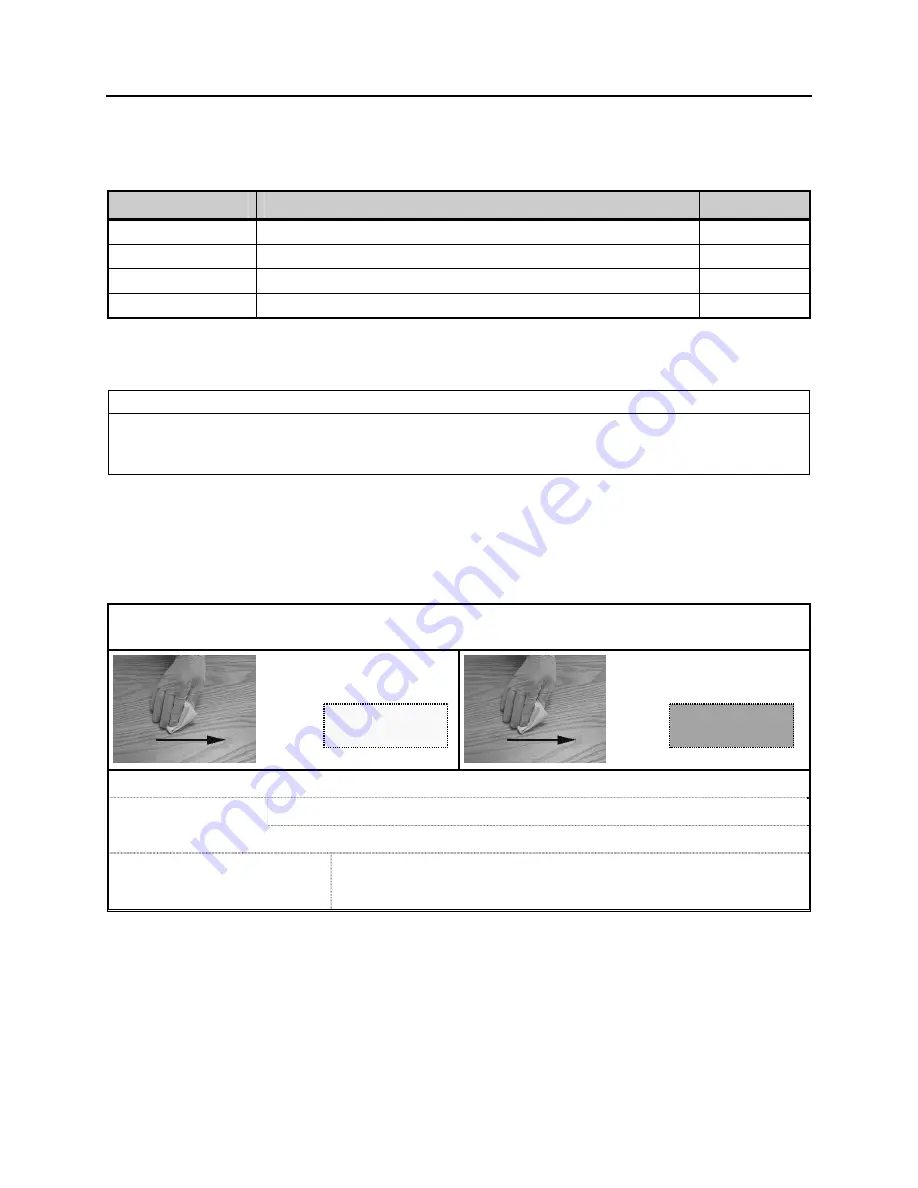
1.
Apply
2.
Dry immediately
3.
Allow drying
Mandatory
Minimum time : Wait for product to evaporate
After 2 hours: Start cleaning operation again
Before applying any other
product
If surface seems dusty, greasy or with finger marks, start cleaning
operation again.
3. Apply Sika Primer 215 (refer to Section D).
CHIX cloth
Blue cloth
Summary of Contents for X3-45 2016
Page 4: ......
Page 16: ...Section 00 GENERAL INFORMATION PA1593 12 FIGURE 12 METRIC US STANDARD CONVERSION TABLE 00005...
Page 17: ...Section 00 GENERAL INFORMATION 13 PA1593 FIGURE 13 CONVERSION CHART 00006...
Page 18: ......
Page 26: ......
Page 58: ......
Page 72: ...Section 04 EXHAUST AND AFTERTREATMENT SYSTEM PA1593 14 7 TORQUE SPECIFICATIONS...
Page 73: ...SECTION 04 EXHAUST AND AFTERTREATMENT SYSTEM PA1593 15...
Page 74: ...Section 04 EXHAUST AND AFTERTREATMENT SYSTEM PA1593 16...
Page 76: ......
Page 96: ......
Page 134: ......
Page 176: ...SECTION 06B ELECTRICAL 38 overcurrent working Circuit 306 shorted to ground...
Page 180: ......
Page 202: ......
Page 205: ...Section 09 PROPELLER SHAFT PA1593 3 FIGURE 1 PROPELLER SHAFT ASSEMBLY 09002...
Page 256: ......
Page 268: ......
Page 295: ...SECTION 16 SUSPENSION PA1593 9 2 5 TORQUE SPECIFICATIONS...
Page 296: ...Section 16 SUSPENSION PA1593 10...
Page 297: ...Section 16 SUSPENSION PA1593 11...
Page 314: ......
Page 380: ......
Page 388: ......
Page 413: ...Section 22 HEATING AND AIR CONDITIONING PA1593 15 FIGURE 18 REFRIGERANT CIRCUIT CENTRAL SYSTEM...
Page 433: ...Section 22 HEATING AND AIR CONDITIONING PA1593 35 FIGURE 36 CENTRAL HEATING SYSTEM COMPONENTS...


