Section 18: BODY
PA1593
63
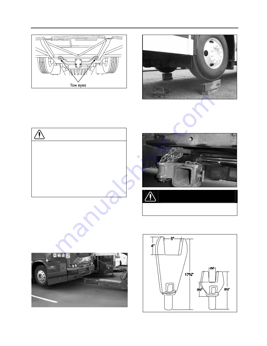
FIGURE 55: TOW EYES UNDER VEHICLE
18401
Disconnect driveshaft or remove both drive
axle shafts to prevent damage to the trans-
mission. Plug axle tube to prevent oil loss.
Refer to Rockwell's
"Maintenance manual
no.5"
annexed at the end of Section 11: Rear
Axle of the maintenance manual.
CAUTION
To prevent damage to the drive train
components, disconnect axle shafts or
driveshaft before towing. Do not attempt to
push or pull-start a vehicle equipped with an
automatic transmission.
Failure to disconnect the driveshaft,
remove the drive axle shafts or lift the drive
wheels off the ground before towing can
cause serious transmission damage and
void the warranty.
The towed vehicle must be lifted from under
the front end only. The tow truck must be
equipped with the proper lifting equipment to
reach under the tow eyes or the front axle
since no other lifting points are recommend-
ed. Lifting and towing from any other point are
unauthorized as it may cause serious dam-
age to the structure. Do not unload or raise
the tag axle when lifting and towing to prevent
overloading the drive axle.
Raise the front of the coach then install
wooden blocks underneath front tires.
Install axle forks and supports onto tow bar,
position axle forks around beam and into tow
eyes, insert chains into tow eyes to secure.
DANGER
Do not carry passengers while the coach is
being towed.
The coach can also be towed by installing
axle forks on the front axle.
FIGURE 56: AXLE FORKS
Summary of Contents for X3-45 2016
Page 4: ......
Page 16: ...Section 00 GENERAL INFORMATION PA1593 12 FIGURE 12 METRIC US STANDARD CONVERSION TABLE 00005...
Page 17: ...Section 00 GENERAL INFORMATION 13 PA1593 FIGURE 13 CONVERSION CHART 00006...
Page 18: ......
Page 26: ......
Page 58: ......
Page 72: ...Section 04 EXHAUST AND AFTERTREATMENT SYSTEM PA1593 14 7 TORQUE SPECIFICATIONS...
Page 73: ...SECTION 04 EXHAUST AND AFTERTREATMENT SYSTEM PA1593 15...
Page 74: ...Section 04 EXHAUST AND AFTERTREATMENT SYSTEM PA1593 16...
Page 76: ......
Page 96: ......
Page 134: ......
Page 176: ...SECTION 06B ELECTRICAL 38 overcurrent working Circuit 306 shorted to ground...
Page 180: ......
Page 202: ......
Page 205: ...Section 09 PROPELLER SHAFT PA1593 3 FIGURE 1 PROPELLER SHAFT ASSEMBLY 09002...
Page 256: ......
Page 268: ......
Page 295: ...SECTION 16 SUSPENSION PA1593 9 2 5 TORQUE SPECIFICATIONS...
Page 296: ...Section 16 SUSPENSION PA1593 10...
Page 297: ...Section 16 SUSPENSION PA1593 11...
Page 314: ......
Page 380: ......
Page 388: ......
Page 413: ...Section 22 HEATING AND AIR CONDITIONING PA1593 15 FIGURE 18 REFRIGERANT CIRCUIT CENTRAL SYSTEM...
Page 433: ...Section 22 HEATING AND AIR CONDITIONING PA1593 35 FIGURE 36 CENTRAL HEATING SYSTEM COMPONENTS...


