Section 22: HEATING AND AIR CONDITIONING
PA1593
7
The condenser coil mounted on the opposite
side of the evaporator is ventilated by four axial
fans. The fan motors are protected by a
manually-resettable 70 amp circuit breaker
(CB7) mounted on the rear junction panel and
accessible from the engine compartment curb-
side door.
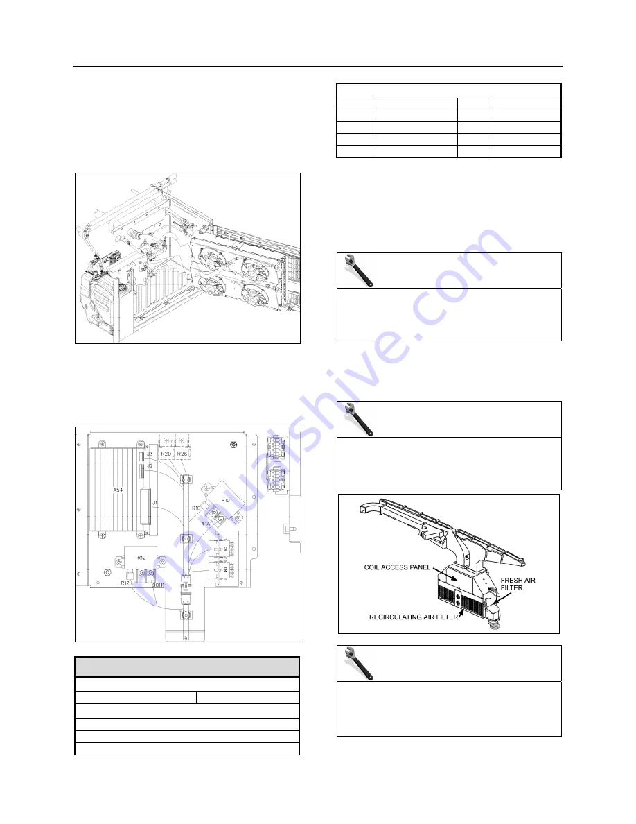
FIGURE 8: CONDENSER COMPARTMENT
22299
Furthermore, the following relays, diodes and
multiplex module are located in the evaporator
compartment (Fig. 9). They are mounted in the
HVAC junction box located inside the evaporator
compartment door.
FIGURE 9: A/C JUNCTION BOX
A/C Junction Box
Multiplex Module
A54 I/O-B
Relays
R10
Condenser Fan Sp. 2
R12 Evaporator
Fan
R20
Water Pump Relay
Diodes
D9 HVAC
D11
Pass. Liq. Sol.
D17
Lugg. 5
th
Compt
D19 Lugg.
2
nd
Compt
D20
Lugg. 1
st
Compt
D25 Evap.
Fan
D30
Water
Pump
D73 Opt.
D80
Opt.
4. HVAC UNIT MAINTENANCE
No special maintenance is required on the
passengers and driver's HVAC units, with the
exception of cleaning their respective coils and air
filters, plus periodic inspection for broken drains,
hoses and charging of system.
MAINTENANCE
Squeeze rubber discharge tubes located
underneath the appropriate compartment to
eliminate the accumulated water and dirt
every three months.
4.1 COIL CLEANING
Check the external surface of the coil at regular
intervals for dirt or any foreign matter.
MAINTENANCE
For the driver's HVAC unit, remove the grill
and the access panels and back flush the coil
every 12,500 miles (20 000 km) or once a year,
whichever comes first
FIGURE 10: DRIVER'S HVAC UNIT COIL ACCESS PANEL
MAINTENANCE
For the passengers’ section evaporator coil,
remove the access panel and back flush the
coil every 12,500 miles (20 000 km) or once a
year, whichever comes first
Summary of Contents for X3-45 2016
Page 4: ......
Page 16: ...Section 00 GENERAL INFORMATION PA1593 12 FIGURE 12 METRIC US STANDARD CONVERSION TABLE 00005...
Page 17: ...Section 00 GENERAL INFORMATION 13 PA1593 FIGURE 13 CONVERSION CHART 00006...
Page 18: ......
Page 26: ......
Page 58: ......
Page 72: ...Section 04 EXHAUST AND AFTERTREATMENT SYSTEM PA1593 14 7 TORQUE SPECIFICATIONS...
Page 73: ...SECTION 04 EXHAUST AND AFTERTREATMENT SYSTEM PA1593 15...
Page 74: ...Section 04 EXHAUST AND AFTERTREATMENT SYSTEM PA1593 16...
Page 76: ......
Page 96: ......
Page 134: ......
Page 176: ...SECTION 06B ELECTRICAL 38 overcurrent working Circuit 306 shorted to ground...
Page 180: ......
Page 202: ......
Page 205: ...Section 09 PROPELLER SHAFT PA1593 3 FIGURE 1 PROPELLER SHAFT ASSEMBLY 09002...
Page 256: ......
Page 268: ......
Page 295: ...SECTION 16 SUSPENSION PA1593 9 2 5 TORQUE SPECIFICATIONS...
Page 296: ...Section 16 SUSPENSION PA1593 10...
Page 297: ...Section 16 SUSPENSION PA1593 11...
Page 314: ......
Page 380: ......
Page 388: ......
Page 413: ...Section 22 HEATING AND AIR CONDITIONING PA1593 15 FIGURE 18 REFRIGERANT CIRCUIT CENTRAL SYSTEM...
Page 433: ...Section 22 HEATING AND AIR CONDITIONING PA1593 35 FIGURE 36 CENTRAL HEATING SYSTEM COMPONENTS...


