Section 22: HEATING AND AIR CONDITIONING
PA1593
20
2. Remove the failed compressor and repair it if
possible.
3. Install new or repaired compressor.
4. Change the filter dryer.
5. Circulate clean R-134a or nitrogen using a
pressurized metal cylinder or a reclaiming
machine to clean out many of the
contaminants collected in the coil valves,
TXV (Thermal Expansion Valve), solenoid
valves, check valves, and any other
mechanical component that may have
collected contaminants.
6. Evacuate and charge the system normally.
7. Run the unit for 8 hours and monitor the
pressure drop across the filter dryer. Also
check the liquid line dryer for signs of
restriction. If the pressure drop across the
filter dryer exceeds 12 to 14 psig (82,75 to
96,5 kPa) with a 40°F (5°C) evaporator coil
temperature, stop the unit and change the
liquid line and suction line filter dryer. After 4
or 5 hours of operation, stop the unit and
replace the filter dryer.
8. After 8 hours of operation, stop the unit and
remove a sample of the compressor oil and
check its color, odor, and acidity, using
instructions supplied above. If the oil is
contaminated, replace the oil and repeat step
7. If the oil is not contaminated, change the
filter dryer again and replace the moisture-
liquid indicator.
9. After approximately 7 days of operation,
recheck the compressor oil for cleanliness
and acidity.
7. CENTRAL A/C SYSTEM COMPONENTS
7.1 COMPRESSOR (CENTRAL SYSTEM)
7.1.1 Belt
Replacement
DANGER
Set the battery master switch to the “Off”
position. For greater safety, set the engine
starter selector switch in engine compartment
to the “Off” position.
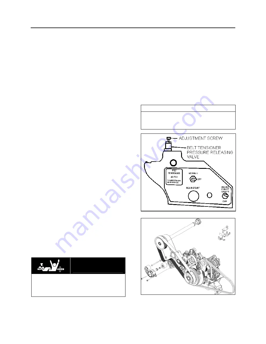
1. Open engine compartment rear doors and
locate the belt tensioner pressure releasing
valve (Fig. 20), mounted above the engine
R.H. side door next to the air pressure
regulator, then turn handle clockwise in
order to release pressure and tension on
belts.
2. Remove the radiator fan driving mechanism
belt (Refer to Section 05: Cooling).
3. Slip the old A/C compressor belts off and
the new ones on.
4. Reset belt tensioner pressure releasing
valve (Fig. 20) to 45 psi (310 kPa) to apply
tension on the new belts as explained in
Section 12.
NOTE
Both belts must always be replaced
simultaneously to ensure an equal distribution
of load on each of them.
FIGURE 20: AIR PRESSURE REGULATOR
FIGURE 21: BELT ARRANGEMENT
Summary of Contents for X3-45 2016
Page 4: ......
Page 16: ...Section 00 GENERAL INFORMATION PA1593 12 FIGURE 12 METRIC US STANDARD CONVERSION TABLE 00005...
Page 17: ...Section 00 GENERAL INFORMATION 13 PA1593 FIGURE 13 CONVERSION CHART 00006...
Page 18: ......
Page 26: ......
Page 58: ......
Page 72: ...Section 04 EXHAUST AND AFTERTREATMENT SYSTEM PA1593 14 7 TORQUE SPECIFICATIONS...
Page 73: ...SECTION 04 EXHAUST AND AFTERTREATMENT SYSTEM PA1593 15...
Page 74: ...Section 04 EXHAUST AND AFTERTREATMENT SYSTEM PA1593 16...
Page 76: ......
Page 96: ......
Page 134: ......
Page 176: ...SECTION 06B ELECTRICAL 38 overcurrent working Circuit 306 shorted to ground...
Page 180: ......
Page 202: ......
Page 205: ...Section 09 PROPELLER SHAFT PA1593 3 FIGURE 1 PROPELLER SHAFT ASSEMBLY 09002...
Page 256: ......
Page 268: ......
Page 295: ...SECTION 16 SUSPENSION PA1593 9 2 5 TORQUE SPECIFICATIONS...
Page 296: ...Section 16 SUSPENSION PA1593 10...
Page 297: ...Section 16 SUSPENSION PA1593 11...
Page 314: ......
Page 380: ......
Page 388: ......
Page 413: ...Section 22 HEATING AND AIR CONDITIONING PA1593 15 FIGURE 18 REFRIGERANT CIRCUIT CENTRAL SYSTEM...
Page 433: ...Section 22 HEATING AND AIR CONDITIONING PA1593 35 FIGURE 36 CENTRAL HEATING SYSTEM COMPONENTS...


