Section 22: HEATING AND AIR CONDITIONING
PA1593
21
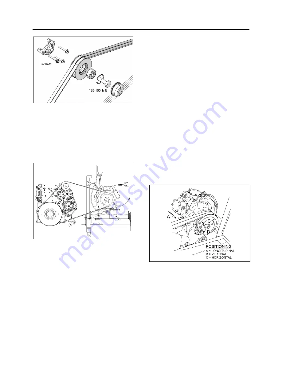
FIGURE 22: IDLER PULLEY INSTALLATION ON VOLVO
D13 ENGINE
7.1.2 Belt Tension Adjustment
Belt tensioning is applied through air bellows
which are adjusted by an air pressure regulating
valve. The correct pressure of 45 psi (310 kPa)
is set at the factory. Periodically verify the
pressure at the regulating valve using a
pressure gauge and correct if necessary.
FIGURE 23: A/C COMPRESSOR BELT ADJUSTMENT
22288
7.1.3 Pulley
Alignment
In order to avoid skipping, disengagement and a
premature wear of compressor belt, it is
necessary to align compressor pulley with the
crankshaft pulley. Before performing the
following procedure, release air from belt
tensioner bellows by means of the air pressure
releasing valve. After completing these
procedures reset belt tensioner air pressure
regulator to 45 psi (310 kPa).
7.1.4 Longitudinal Compressor Alignment
1. Rest an extremity of a straight edge of
approximately 46 inches (117 cm) against
the upper part of the outer face of crankshaft
pulley, positioning the other end close to the
compressor clutch pulley (Figs. 24 & 25).
2. Check the distance between each extremity
of straight edge (1. Fig. 25) and the first
drive belt. If they are different, loosen the
compressor support bolts and with a
hammer, knock support to slide it in order to
obtain the same distance; then tighten bolts.
7.1.5 Horizontal Compressor Alignment
1. Rest an extremity of the straight edge
against the upper part of the outer face of
compressor pulley, positioning the other end
close to the crankshaft pulley.
2. Check the distance between each extremity
of straight edge (1, Fig. 25) and drive belt. If
they are different, loosen the pillow block
compressor bolts and with a hammer, knock
compressor pillow block to slide it, in order
to obtain the same distance; then tighten
bolts.
FIGURE 24: COMPRESSOR ALIGNMENT
22072
7.1.6 Vertical Compressor Alignment
Rest a short "angle and level indicator" on the
outer side face of the crankshaft pulley, adjust
the level indicator inclination at 0
o
and check if
the compressor pulley is at same angle (Fig.
24). If it is not the same, shim under the
appropriate pillow block in order to obtain the
correct angle.
Summary of Contents for X3-45 2016
Page 4: ......
Page 16: ...Section 00 GENERAL INFORMATION PA1593 12 FIGURE 12 METRIC US STANDARD CONVERSION TABLE 00005...
Page 17: ...Section 00 GENERAL INFORMATION 13 PA1593 FIGURE 13 CONVERSION CHART 00006...
Page 18: ......
Page 26: ......
Page 58: ......
Page 72: ...Section 04 EXHAUST AND AFTERTREATMENT SYSTEM PA1593 14 7 TORQUE SPECIFICATIONS...
Page 73: ...SECTION 04 EXHAUST AND AFTERTREATMENT SYSTEM PA1593 15...
Page 74: ...Section 04 EXHAUST AND AFTERTREATMENT SYSTEM PA1593 16...
Page 76: ......
Page 96: ......
Page 134: ......
Page 176: ...SECTION 06B ELECTRICAL 38 overcurrent working Circuit 306 shorted to ground...
Page 180: ......
Page 202: ......
Page 205: ...Section 09 PROPELLER SHAFT PA1593 3 FIGURE 1 PROPELLER SHAFT ASSEMBLY 09002...
Page 256: ......
Page 268: ......
Page 295: ...SECTION 16 SUSPENSION PA1593 9 2 5 TORQUE SPECIFICATIONS...
Page 296: ...Section 16 SUSPENSION PA1593 10...
Page 297: ...Section 16 SUSPENSION PA1593 11...
Page 314: ......
Page 380: ......
Page 388: ......
Page 413: ...Section 22 HEATING AND AIR CONDITIONING PA1593 15 FIGURE 18 REFRIGERANT CIRCUIT CENTRAL SYSTEM...
Page 433: ...Section 22 HEATING AND AIR CONDITIONING PA1593 35 FIGURE 36 CENTRAL HEATING SYSTEM COMPONENTS...


