Section 22: HEATING AND AIR CONDITIONING
PA1593
24
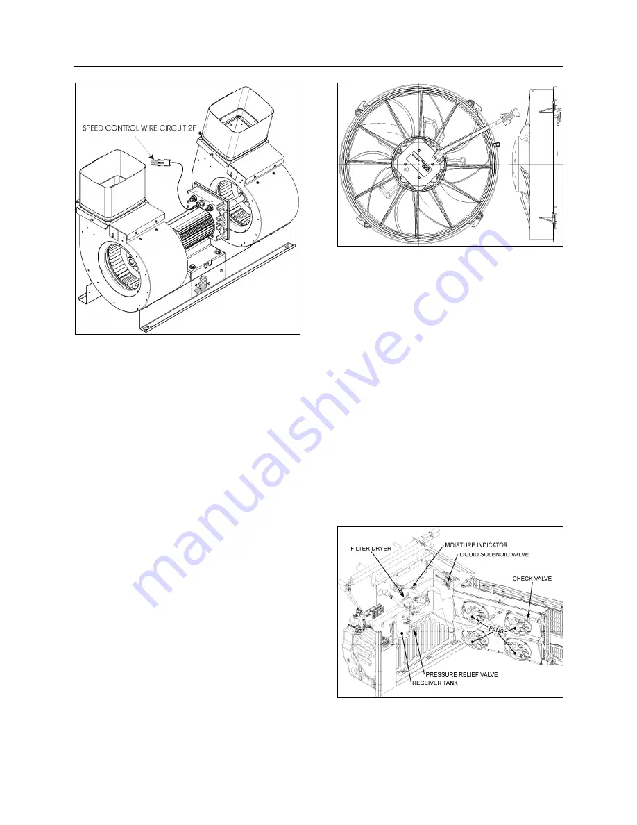
FIGURE 28: EVAPORATOR MOTOR ASSEMBLY
7.4 CONDENSER
The central A/C system condenser coil is hinge
mounted on the R.H. side of the vehicle on the
A/C condenser door (Fig. 30). Since
condenser’s purpose is to dissipate heat from
the hot refrigerant, it is important to keep the
cooling coils and fins clean. A clogged coil will
cause high discharge pressure and insufficient
cooling.
7.4.1 Condenser Fan Motors
Four brushless fan motors (Fig. 29), 28.5 V -
(0.6 HP - 0.42 kW) are installed in the
condenser compartment on R.H. side of vehicle
in order to ventilate the condenser coil. They are
mounted on a support, fastened to the door. The
fans pull outside air through the condenser coil
and discharge it through an opening at bottom of
compartment. When temperature drops inside
condenser, the pressure in the refrigerant line
also drops and it is, therefore, no longer
required to cool condenser. Consequently, when
pressure drops to 130 psi, the motors will run at
low speed and if the pressure continues to drop
to 90 psi, a pressure switch stops the motors so
that fans do not operate needlessly. When
pressure rises to 120 psi, the pressure switch
reactivates the motors. If the pressure rises to
170 psi, the motors will switch to high speed.
For details about electrical wiring, refer to
“A/C
and Heat system”
in the master wiring diagram.
FIGURE 29: CONDENSER FAN MOTOR
22322
7.4.2 Condenser Fan Motor Removal
1. Set the battery master switch to the
“Off”
position.
2. Disconnect wiring from terminals on motor.
Tag each wire to aid in identification at time
of reconnection.
3. Remove the four hexagonal head cap
screws retaining the fan motor assembly to
the mounting support.
4. Remove the motor.
7.5 RECEIVER
TANK
The receiver tank is located in the condenser
compartment (Fig. 30). The function of the
receiver tank is to store the liquid refrigerant.
During normal operation, the level of the
refrigerant should be approximately at the mid-
point of the lower sight glass.
FIGURE 30: A/C CONDENSER COMPARTMENT
22323
In case of extreme pressure there will be a rise
in the liquid receiver tank. A pressure relief valve
Summary of Contents for X3-45 2016
Page 4: ......
Page 16: ...Section 00 GENERAL INFORMATION PA1593 12 FIGURE 12 METRIC US STANDARD CONVERSION TABLE 00005...
Page 17: ...Section 00 GENERAL INFORMATION 13 PA1593 FIGURE 13 CONVERSION CHART 00006...
Page 18: ......
Page 26: ......
Page 58: ......
Page 72: ...Section 04 EXHAUST AND AFTERTREATMENT SYSTEM PA1593 14 7 TORQUE SPECIFICATIONS...
Page 73: ...SECTION 04 EXHAUST AND AFTERTREATMENT SYSTEM PA1593 15...
Page 74: ...Section 04 EXHAUST AND AFTERTREATMENT SYSTEM PA1593 16...
Page 76: ......
Page 96: ......
Page 134: ......
Page 176: ...SECTION 06B ELECTRICAL 38 overcurrent working Circuit 306 shorted to ground...
Page 180: ......
Page 202: ......
Page 205: ...Section 09 PROPELLER SHAFT PA1593 3 FIGURE 1 PROPELLER SHAFT ASSEMBLY 09002...
Page 256: ......
Page 268: ......
Page 295: ...SECTION 16 SUSPENSION PA1593 9 2 5 TORQUE SPECIFICATIONS...
Page 296: ...Section 16 SUSPENSION PA1593 10...
Page 297: ...Section 16 SUSPENSION PA1593 11...
Page 314: ......
Page 380: ......
Page 388: ......
Page 413: ...Section 22 HEATING AND AIR CONDITIONING PA1593 15 FIGURE 18 REFRIGERANT CIRCUIT CENTRAL SYSTEM...
Page 433: ...Section 22 HEATING AND AIR CONDITIONING PA1593 35 FIGURE 36 CENTRAL HEATING SYSTEM COMPONENTS...


