Section 22: HEATING AND AIR CONDITIONING
PA1593
36
8. CENTRAL HEATING SYSTEM
As seen earlier in this section, the vehicle
interior is pressurized by its Heating, Ventilation
and Air Conditioning (HVAC) system. The
vehicle interior should always be slightly
pressurized to prevent cold and moisture from
entering. Air flow and controls divide the vehicle
into two areas: driver’s area and passenger’s
area.
The schematic of figure 36 shows the central
heating system with its components.
8.1
DRAINING HEATING SYSTEM
To drain the entire system, refer to Section 05,
“Cooling
”. If only the driver’s or main heater core
must be drained, refer to the following
instructions.
Draining Driver’s Heater Core
1. Stop engine and allow engine coolant to
cool.
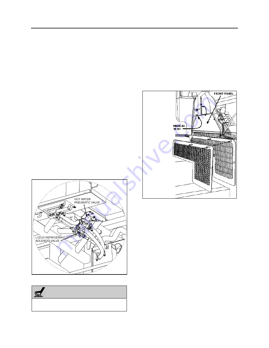
2. Locate the normally open water pneumatic
valve on the ceiling of the spare wheel
compartment (Fig. 37), move the pilot-
solenoid valve red tab to close the valve.
FIGURE 37: CEILING OF THE SPARE WHEEL
COMPARTMENT
WARNING
Before proceeding with the following steps,
check that coolant has cooled down.
3. Loosen hose clamp, install an appropriate
container to recover coolant, and
disconnect silicone hose from water
solenoid valve.
4. From inside of vehicle, remove the two
finishing panels in front of unit. Remove the
three screws fixing the unit front panel.
Open the manual vent located inside the
HVAC unit, on the driver’s side (Fig. 38) to
ensure an efficient draining.
FIGURE 38: DRIVER'S HVAC UNIT
Draining Main Heater Core
1. Stop engine and allow engine coolant to
cool.
2. Close both heater line shutoff valves.
On X Series vehicles
, the valves are located in
the engine compartment. One is on the L.H. side
of compartment in front of the radiator and the
other valve is located under the radiator fan
gearbox (Fig. 39).
Summary of Contents for X3-45 2016
Page 4: ......
Page 16: ...Section 00 GENERAL INFORMATION PA1593 12 FIGURE 12 METRIC US STANDARD CONVERSION TABLE 00005...
Page 17: ...Section 00 GENERAL INFORMATION 13 PA1593 FIGURE 13 CONVERSION CHART 00006...
Page 18: ......
Page 26: ......
Page 58: ......
Page 72: ...Section 04 EXHAUST AND AFTERTREATMENT SYSTEM PA1593 14 7 TORQUE SPECIFICATIONS...
Page 73: ...SECTION 04 EXHAUST AND AFTERTREATMENT SYSTEM PA1593 15...
Page 74: ...Section 04 EXHAUST AND AFTERTREATMENT SYSTEM PA1593 16...
Page 76: ......
Page 96: ......
Page 134: ......
Page 176: ...SECTION 06B ELECTRICAL 38 overcurrent working Circuit 306 shorted to ground...
Page 180: ......
Page 202: ......
Page 205: ...Section 09 PROPELLER SHAFT PA1593 3 FIGURE 1 PROPELLER SHAFT ASSEMBLY 09002...
Page 256: ......
Page 268: ......
Page 295: ...SECTION 16 SUSPENSION PA1593 9 2 5 TORQUE SPECIFICATIONS...
Page 296: ...Section 16 SUSPENSION PA1593 10...
Page 297: ...Section 16 SUSPENSION PA1593 11...
Page 314: ......
Page 380: ......
Page 388: ......
Page 413: ...Section 22 HEATING AND AIR CONDITIONING PA1593 15 FIGURE 18 REFRIGERANT CIRCUIT CENTRAL SYSTEM...
Page 433: ...Section 22 HEATING AND AIR CONDITIONING PA1593 35 FIGURE 36 CENTRAL HEATING SYSTEM COMPONENTS...


