Section 22: HEATING AND AIR CONDITIONING
PA1593
37
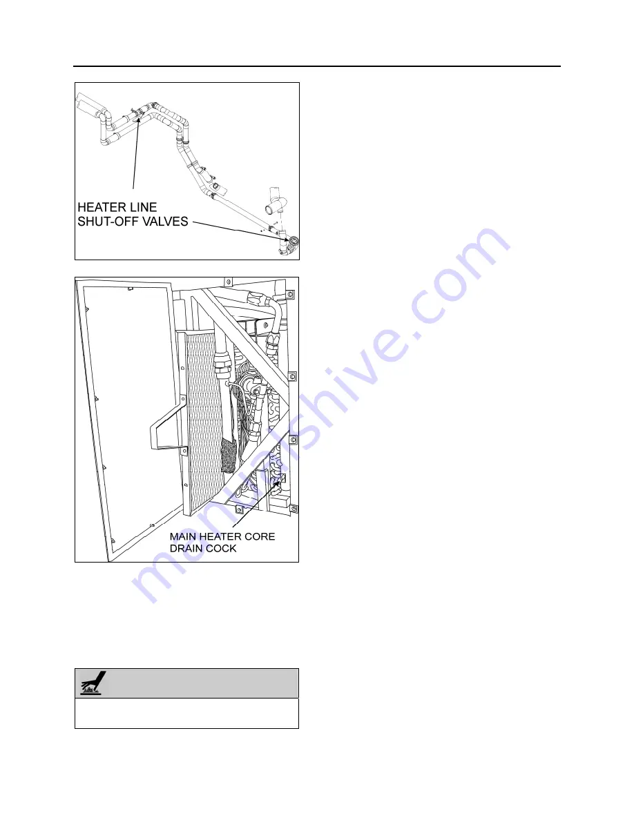
FIGURE 39: HEATER LINE SHUT-OFF VALVES
FIGURE 40: EVAPORATOR COMPARTMENT
3. The main heater core drain cock is located
in the evaporator compartment. To access
the valve on X3-45 coaches, open baggage
compartment door located in front of the
evaporator compartment (L.H. side). Open
access panel by turning the three screws of
panel ¼ of a turn.
WARNING
Before proceeding with the following steps,
check that coolant has cooled down.
4. Open drain cock in bottom of heater core,
you can unfasten a hose connection on top
of heater core (Fig.40) in order to allow air
to enter while draining.
8.2
FILLING HEATING SYSTEM
1. Ensure that the drain hose is reconnected
and the manual vent and drain cock are
closed.
2. Open the surge tank filler cap and slowly fill
the system to level of filler neck.
3. After initial filling, the water shut-off valves
should be open and the water recirculating
pump should be energized to assist in
circulating coolant through the heating
system. To perform this operation, start the
engine, switch on the HVAC control unit,
both driver and passengers’ sections, and
set temperature to the maximum position in
order to request the heating mode in each
of these sections.
4. When coolant level drops below the surge
tank filler neck, slowly fill the system to level
of filler neck.
5. Once the level has been stabilized, replace
cap.
8.3
BLEEDING HEATING SYSTEM
Whenever the heating system has been drained
and refilled, or the system has run low on
coolant and coolant has been added, it is
necessary to bleed air from heating system.
Locate the manual vent illustrated in Figure 38,
and open momentarily until no air escapes from
the line.
8.4 SOLDERING
Before soldering any part of the system, make
sure the area is well ventilated. Use (stay clean)
flux sparingly and apply solder (95-5 round wire
1/8 inch). After completing repairs, test for leaks.
When using heat at or near a valve, wrap with
water saturated rag to prevent overheating of
vital parts.
Summary of Contents for X3-45 2016
Page 4: ......
Page 16: ...Section 00 GENERAL INFORMATION PA1593 12 FIGURE 12 METRIC US STANDARD CONVERSION TABLE 00005...
Page 17: ...Section 00 GENERAL INFORMATION 13 PA1593 FIGURE 13 CONVERSION CHART 00006...
Page 18: ......
Page 26: ......
Page 58: ......
Page 72: ...Section 04 EXHAUST AND AFTERTREATMENT SYSTEM PA1593 14 7 TORQUE SPECIFICATIONS...
Page 73: ...SECTION 04 EXHAUST AND AFTERTREATMENT SYSTEM PA1593 15...
Page 74: ...Section 04 EXHAUST AND AFTERTREATMENT SYSTEM PA1593 16...
Page 76: ......
Page 96: ......
Page 134: ......
Page 176: ...SECTION 06B ELECTRICAL 38 overcurrent working Circuit 306 shorted to ground...
Page 180: ......
Page 202: ......
Page 205: ...Section 09 PROPELLER SHAFT PA1593 3 FIGURE 1 PROPELLER SHAFT ASSEMBLY 09002...
Page 256: ......
Page 268: ......
Page 295: ...SECTION 16 SUSPENSION PA1593 9 2 5 TORQUE SPECIFICATIONS...
Page 296: ...Section 16 SUSPENSION PA1593 10...
Page 297: ...Section 16 SUSPENSION PA1593 11...
Page 314: ......
Page 380: ......
Page 388: ......
Page 413: ...Section 22 HEATING AND AIR CONDITIONING PA1593 15 FIGURE 18 REFRIGERANT CIRCUIT CENTRAL SYSTEM...
Page 433: ...Section 22 HEATING AND AIR CONDITIONING PA1593 35 FIGURE 36 CENTRAL HEATING SYSTEM COMPONENTS...


