Section 03: FUEL SYSTEM
PA1593
3
1.
FUEL SYSTEM WITH VOLVO D13 ENGINE
1.1 DESCRIPTION
NOTE
For additional information concerning Volvo D13 engine components or engine-related components,
consult Volvo Trucks Canada or Volvo Trucks North America Web Site under: Parts & Service. On
Volvo web site, you will find detailed service procedures for parts replacement, repair and
maintenance.
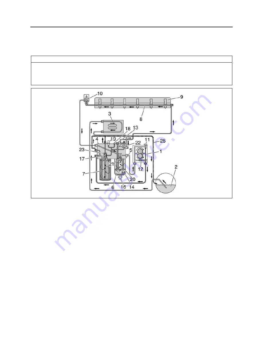
FIGURE 1: FUEL SYSTEM SCHEMATIC (VOLVO D13 ENGINE)
03086
Fuel is drawn up the fuel lines by the supply
pump (1) through the pickup tube in the tank (2)
and through the Engine Electronic Control Unit
(EECU) cooling coil (3) and into the fuel filter
housing (4). The fuel housing is equipped with a
primary fuel filter (fuel/water separator)
consisting of a filter cartridge and a water
separation bowl.
The supply pump (1) forces the fuel into the fuel
filter housing through the secondary filter (main)
to a cylinder head longitudinal gallery (8). This
channel supplies each unit injector (9) with
pressurized fuel by a circular groove around
each unit injector in the cylinder head. The
overflow valve (10) controls the fuel supply
pressure to the unit injectors.
The return fuel from the overflow valve (10) is
returned back to the fuel filler housing and is
mixed with the fuel from the fuel tank in a
channel within the fuel filter housing (4).
Supply Pump Valves
Two valves are located in the supply pump (1).
The safety valve (11) allows fuel to flow back to
the suction side when the pressure becomes too
high, e.g., if the fuel filter is blocked or is too
restricted. The non-return valve (12) opens
when the hand-priming pump is used.
Automatic Bleeding
If air gets into the system, it is bled when the
engine starts. During bleeding, air is pressed out
through the fuel filter housing over to the fuel
tank through the return line (25). Bleeding for
the filter replacement is controlled by valves (17)
and (23).
Summary of Contents for X3-45 2016
Page 4: ......
Page 16: ...Section 00 GENERAL INFORMATION PA1593 12 FIGURE 12 METRIC US STANDARD CONVERSION TABLE 00005...
Page 17: ...Section 00 GENERAL INFORMATION 13 PA1593 FIGURE 13 CONVERSION CHART 00006...
Page 18: ......
Page 26: ......
Page 58: ......
Page 72: ...Section 04 EXHAUST AND AFTERTREATMENT SYSTEM PA1593 14 7 TORQUE SPECIFICATIONS...
Page 73: ...SECTION 04 EXHAUST AND AFTERTREATMENT SYSTEM PA1593 15...
Page 74: ...Section 04 EXHAUST AND AFTERTREATMENT SYSTEM PA1593 16...
Page 76: ......
Page 96: ......
Page 134: ......
Page 176: ...SECTION 06B ELECTRICAL 38 overcurrent working Circuit 306 shorted to ground...
Page 180: ......
Page 202: ......
Page 205: ...Section 09 PROPELLER SHAFT PA1593 3 FIGURE 1 PROPELLER SHAFT ASSEMBLY 09002...
Page 256: ......
Page 268: ......
Page 295: ...SECTION 16 SUSPENSION PA1593 9 2 5 TORQUE SPECIFICATIONS...
Page 296: ...Section 16 SUSPENSION PA1593 10...
Page 297: ...Section 16 SUSPENSION PA1593 11...
Page 314: ......
Page 380: ......
Page 388: ......
Page 413: ...Section 22 HEATING AND AIR CONDITIONING PA1593 15 FIGURE 18 REFRIGERANT CIRCUIT CENTRAL SYSTEM...
Page 433: ...Section 22 HEATING AND AIR CONDITIONING PA1593 35 FIGURE 36 CENTRAL HEATING SYSTEM COMPONENTS...


