Section 03: FUEL SYSTEM
PA1593
7
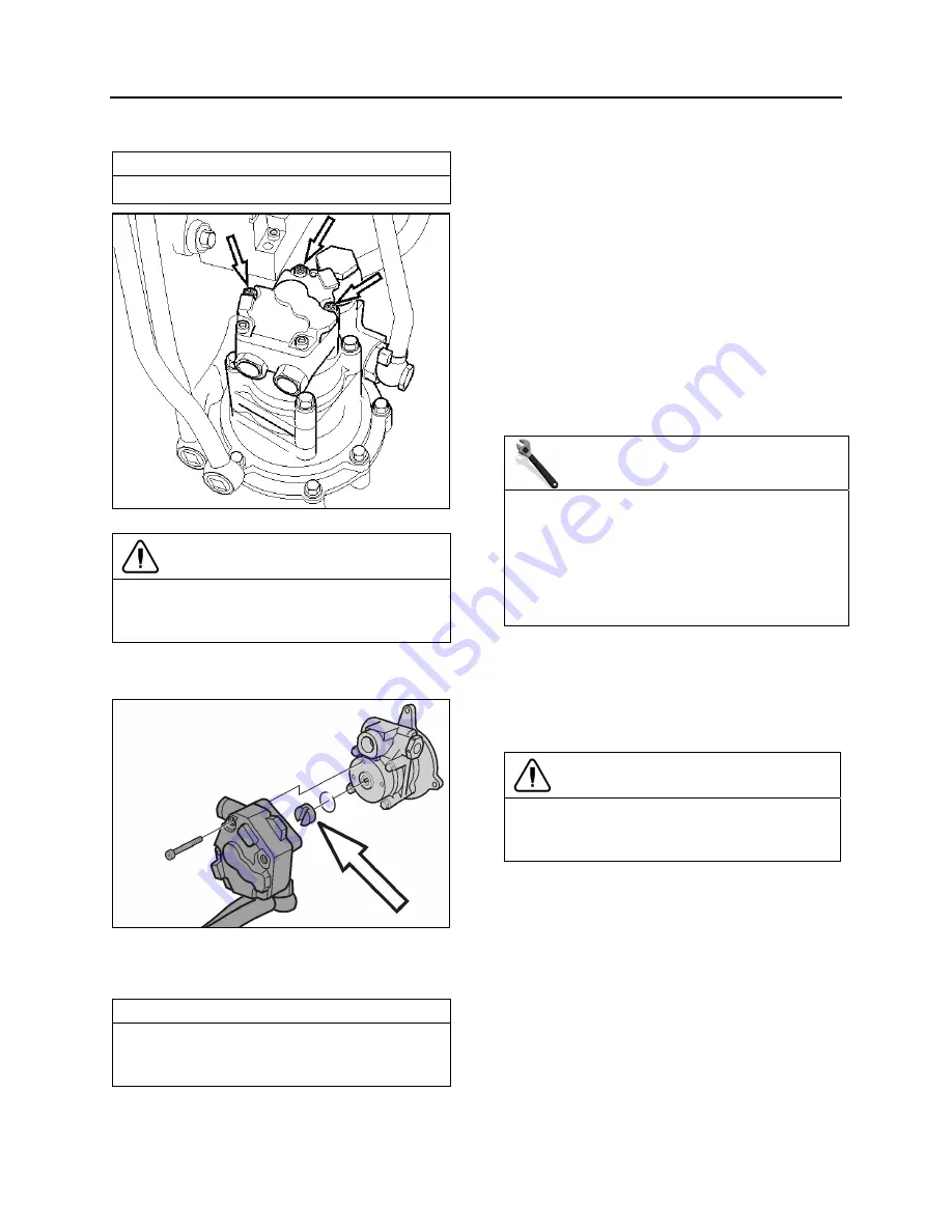
Remove the fuel pump.
NOTE
Only unfasten the bolts marked with arrows.
FIGURE 6: FUEL PUMP REMOVAL
CAUTION
Ensure to clean around the head of the bolts.
Debris will prevent the tool from fitting properly
and cause damage to the fasteners..
Check that the adapter and fuel pump drive
axle are not damaged.
FIGURE 7: FUEL PUMP DRIVE AXLE
Install the fuel pump. Torque-tighten bolts to
specification.
NOTE
Use a new sealing ring. Check that the fuel
pump drive axle sits correctly in the power
steering pump.
Using the hand primer on the fuel filter
housing, prime the fuel system.
Start the engine and let run for 5 minutes.
Make sure that there are no leaks.
2.
FUEL LINES AND
FLEXIBLE HOSES
Make a visual check for fuel leaks at all engine-
mounted fuel lines and connections and at the
fuel tank suction and return lines. Since fuel
tanks are susceptible to road hazards, leaks in
this area may best be detected by checking for
accumulation of fuel under the tank. Engine
performance and auxiliary equipment is greatly
dependent on the ability of flexible hoses to
transfer lubricating oil, air, coolant and fuel oil.
Diligent maintenance of hoses is an important
step in ensuring efficient, economical and safe
operation of engine and related equipment.
MAINTENANCE
Check hoses daily as part of the pre-start-up
inspection. Examine hoses for leaks and check
all fittings, clamps and ties carefully. Make sure
that the hoses are not resting on or touching
shafts, couplings, and heated surfaces,
including exhaust manifolds, any sharp edges
or other obviously hazardous areas.
Since all machinery vibrates and moves to a
certain extent, clamps and ties can fatigue with
age. To ensure continued proper support,
inspect fasteners frequently and tighten or
replace them as necessary. Refer to the
schematic diagram of the fuel system (Fig. 1).
CAUTION
Oil level above the dipstick full mark or a
decrease in lube oil consumption may indicate
internal fuel leaks. Check oil level frequently.
3. FUEL
TANK
X3-45 coaches are equipped with a high-density
cross-link polyethylene fuel tank with a capacity
of 208 US gallons (787 liters).
The fuel filling access door is located on the
R.H. side of vehicle providing easy fuel filling.
A pressure relief valve on the fuel tank
connection-panel relieves high-pressure buildup
and an overflow tube allows offset air in the tank
to escape during filling. For 95% of the tank
volume, 5% of tank inside space is kept filled
with air with no exit opening, allowing for a fuel
Summary of Contents for X3-45 2016
Page 4: ......
Page 16: ...Section 00 GENERAL INFORMATION PA1593 12 FIGURE 12 METRIC US STANDARD CONVERSION TABLE 00005...
Page 17: ...Section 00 GENERAL INFORMATION 13 PA1593 FIGURE 13 CONVERSION CHART 00006...
Page 18: ......
Page 26: ......
Page 58: ......
Page 72: ...Section 04 EXHAUST AND AFTERTREATMENT SYSTEM PA1593 14 7 TORQUE SPECIFICATIONS...
Page 73: ...SECTION 04 EXHAUST AND AFTERTREATMENT SYSTEM PA1593 15...
Page 74: ...Section 04 EXHAUST AND AFTERTREATMENT SYSTEM PA1593 16...
Page 76: ......
Page 96: ......
Page 134: ......
Page 176: ...SECTION 06B ELECTRICAL 38 overcurrent working Circuit 306 shorted to ground...
Page 180: ......
Page 202: ......
Page 205: ...Section 09 PROPELLER SHAFT PA1593 3 FIGURE 1 PROPELLER SHAFT ASSEMBLY 09002...
Page 256: ......
Page 268: ......
Page 295: ...SECTION 16 SUSPENSION PA1593 9 2 5 TORQUE SPECIFICATIONS...
Page 296: ...Section 16 SUSPENSION PA1593 10...
Page 297: ...Section 16 SUSPENSION PA1593 11...
Page 314: ......
Page 380: ......
Page 388: ......
Page 413: ...Section 22 HEATING AND AIR CONDITIONING PA1593 15 FIGURE 18 REFRIGERANT CIRCUIT CENTRAL SYSTEM...
Page 433: ...Section 22 HEATING AND AIR CONDITIONING PA1593 35 FIGURE 36 CENTRAL HEATING SYSTEM COMPONENTS...


